Software for Windows
Science with your Sound Card!


Features:
Oscilloscope
Spectrum Analyzer
8-Channel
Signal Generator
(Absolutely FREE!)
Spectrogram
Pitch Tracker
Pitch-to-MIDI
DaqMusiq Generator
(Free Music... Forever!)
Engine Simulator
LCR Meter
Remote Operation
DC Measurements
True RMS Voltmeter
Sound Level Meter
Frequency Counter
Period
Event
Spectral Event
Temperature
Pressure
MHz Frequencies
Data Logger
Waveform Averager
Histogram
Post-Stimulus Time
Histogram (PSTH)
THD Meter
IMD Meter
Precision Phase Meter
Pulse Meter
Macro System
Multi-Trace Arrays
Trigger Controls
Auto-Calibration
Spectral Peak Track
Spectrum Limit Testing
Direct-to-Disk Recording
Accessibility
Data Logger
Waveform Averager
Histogram
Post-Stimulus Time
Histogram (PSTH)
THD Meter
IMD Meter
Precision Phase Meter
Pulse Meter
Macro System
Multi-Trace Arrays
Trigger Controls
Auto-Calibration
Spectral Peak Track
Spectrum Limit Testing
Direct-to-Disk Recording
Accessibility
Applications:
Frequency response
Distortion measurement
Speech and music
Microphone calibration
Loudspeaker test
Auditory phenomena
Musical instrument tuning
Animal sound
Evoked potentials
Rotating machinery
Automotive
Product test
Contact us about
your application!
Sound Card Input Range and Limiter Circuits
Most sound cards can only handle input signals over a range of +/-2.5 volts. Although they may be able to tolerate somewhat larger signals, information about the exact limits is not generally available to the user and shouldn't be depended upon.
Instead, you can use a simple input limiter circuit to protect your sound card from potentially damaging voltages. The basic concept is illustrated here:
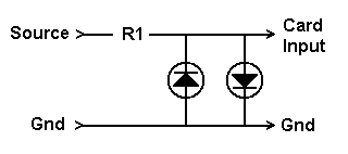
An LED (Light Emitting Diode) behaves like a very high resistance when voltage is applied in the reverse direction, just like a conventional diode. In the forward direction, an LED does not conduct until the voltage rises above a threshold which is characteristic of the LED type, especially its color. Approximate thresholds for some common LEDs are:
- Red = 1.5 V
- Yellow = 1.8 V
- Green = 1.9 V
When an LED is conducting, the voltage across it remains nearly constant at the threshold voltage. (This assumes the presence of a current limiting resistor, here served by R1).
Since the LEDs in this circuit are connected in reverse parallel, both positive and negative voltages are limited. For example, with two green LEDs the voltage to the sound card would be limited to about +/-1.9 volts... safe for all sound card Line inputs.
Selection of the R1 value requires some consideration of the range of voltages you need to handle. Typical LEDs can handle 20 mA, so R1 should be selected such that at the maximum anticipated voltage there will be no more than 20 mA flowing through the resistor. The voltage across the resistor is the applied voltage less the LED voltage.
Let's say you want to handle +/-24 volts, using green LEDs. Then the voltage across R1 will be 24 - 1.9 = 22.1 V. For a current of 20 mA at this voltage, the resistance (via Ohm's Law) would be:
R1 = V / I
R1 = 22.1 / 0.020
R1 = 1105 ohms
You would round this to the nearest standard value of 1100 ohms.
Note that this only assures that the sound card input is protected, not that you will get an accurate measurement. Measurements are only accurate up to the LED threshold. (But see below.)
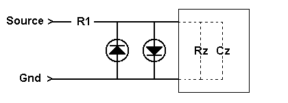
You could use this same procedure for a higher voltage range. However, this simple formula ignores the effective input resistance of the sound card, which is typically in the 50,000 ohm (50K) range. That resistance Rz, together with R1, make up a voltage divider that reduces the signal seen by the sound card. (Ignore for a moment the capacitive component Cz.)
For example, suppose R1 is 10K to handle inputs up to about 200 volts. (CAUTION: See below!) If the input impedance is 50K, then the voltage to the sound card is reduced by the fraction:
G = Rz / (R1 + Rz)
G = 50K / (10K + 50K)
G = 0.833
You would account for this by setting it as the gain factor in the External Gain dialog, found in the Calibration menu.
Input voltages can be measured accurately up to the LED threshold divided by G. In this case, with a green LED, that would be 1.9 / 0.833 = +/-2.28 volts.
One guiding principle of measurement systems is that they should not disturb the systems being measured. That means that the input impedance of the measurement system must be much higher than the values encountered in the measured system.
In practice, 1 Megohm is a realistic input impedance. It is standard on benchtop oscilloscopes. You can make a 1 Megohm input stage for your sound card by selecting R1 such that R1 + Rz = 1 Megohm.
For the example sound card measured in the Impedance Measurement topic, the resistive part of the input impedance was 67K. So R1 would be 1000K - 67K = 933K. That's not a standard resistor value, so you might need to use a couple of resistors in series, depending on how close you want to hit 1 Megohm. For most work, the exact value doesn't matter as long as it is "high", so we'll assume 910K here.
Now the voltage divider fraction is:
G = Rz / (R1 + Rz)
G = 67 / (910 + 67)
G = 67 / 977
G = 0.0686
That's the value you'd use for the External Gain factor.
That reduction also means that you'll lose some resolution at low input voltages. That G value represents a division of the signal by 1/G or 14.6, which amounts to a loss of nearly 4 bits (divide by 16) out of 16 bits total. But that's not really a problem for the vast majority of measurements; in fact, many laboratory-type data acquisition boards are 12-bit systems. You'll still get better than 1 part in 4000 resolution, which beats most benchtop multimeters, and is much better that the 8 bits (1 part in 256) offered by many oscilloscopes.
But with this large R1 resistor value you need to consider the capacitive portion of the input impedance. Without compensation, the input circuit would become a low-pass filter with a cutoff in the low kHz range.
To compensate, you need to add a small capacitor in parallel with R1. We'll call this C1, and the capacitive part of the sound card input impedance will be Cz. Proper compensation is achieved when:
R1 * C1 = Rz * Cz
Rearranging terms:
C1 = Cz * Rz / R1
As noted in the Impedance Measurement topic, the effective value of Cz is dominated by cable capacitance. Thus, you should measure Cz using the exact same cable (or at least the same type and same length) that will become a part of your measurement setup. Only the cable between R1 and the sound card input is important here.
For the example sound card with a 6 foot cable:
Cz = 627 pF * 67K / 910K
Cz = 46 pF
Use the nearest standard value, which is 47 pF. For critical work this can be made adjustable with a small "trimmer" capacitor. You can check the frequency response using the same swept response method discussed in the Input Impedance section for determining the input capacitance.
What about the maximum input voltage with this large R1? In principle, to get the LED limit of 20 mA through 910K would require 18200 volts, and the resistor would have to dissipate 364 watts! This is way beyond the limits of standard components, and is definitely not recommended. But it does assure us that popping the LEDs is the last thing you need to be concerned about when measuring voltages.
The maximum voltage before the LED limiter threshold would be 1.9 / G = +/-27.74 volts. That's the largest peak (positive or negative) voltage you can measure, equivalent to about 19.6 volts RMS.
If you need to measure higher voltages, you can either increase R1, or you can reduce the effective Rz by adding a resistor in parallel with the LEDs. In either case, the value of C1 will need to be recalculated.
Note that as R1 gets higher, there will be a greater tendency for electrostatic hum pickup from the environment, so you may need to experiment with shielding. This approach is probably best avoided unless you really need a higher input impedance.
Shielded x10 probes are readily available for conventional benchtop oscilloscopes with 1 Megohm input impedance. The probe provides 10 Megohm effective input impedance and a 10:1 attenuation.
If you have access to one of these, you may want to experiment with using it ahead of the 1 Megohm input stage just discussed. You may find that the capacitance compensation is not optimal, since the probe is designed to work into an input capacitance of around 20 pF or so. But it should be fairly close, and can be adjusted with a small screwdriver trimmer on the probe.
USE EXTREME CAUTION when connecting to external voltages. You must make ABSOLUTELY CERTAIN that the common ground of the circuit you want to measure is the same as the computer case (and sound card connector) ground. If you are not sure (or even if you think you are), use an inexpensive battery-operated multi-meter to measure the voltage difference between the two before connecting anything. Start with the meter on the maximum AC Volts range. If you read zero, reduce the range and repeat. If there is no AC voltage on any range, switch to DC Volts and repeat. If there is still no voltage, switch to Ohms... you should read a very low value, not more than a few ohms. That verifies that the grounds are indeed connected.
- Back to Sound Card Impedance Measurement
- Ahead to AC-to-DC Input Level Shifter and Limiter
- Daqarta Help Contents
- Daqarta Help Index
- Daqarta Downloads
- Daqarta Home Page
- Purchase Daqarta
Questions? Comments? Contact us!
We respond to ALL inquiries, typically within 24 hrs.INTERSTELLAR RESEARCH:
Over 35 Years of Innovative Instrumentation
© Copyright 2007 - 2023 by Interstellar Research
All rights reserved