Software for Windows
Science with your Sound Card!


Features:
Oscilloscope
Spectrum Analyzer
8-Channel
Signal Generator
(Absolutely FREE!)
Spectrogram
Pitch Tracker
Pitch-to-MIDI
DaqMusiq Generator
(Free Music... Forever!)
Engine Simulator
LCR Meter
Remote Operation
DC Measurements
True RMS Voltmeter
Sound Level Meter
Frequency Counter
Period
Event
Spectral Event
Temperature
Pressure
MHz Frequencies
Data Logger
Waveform Averager
Histogram
Post-Stimulus Time
Histogram (PSTH)
THD Meter
IMD Meter
Precision Phase Meter
Pulse Meter
Macro System
Multi-Trace Arrays
Trigger Controls
Auto-Calibration
Spectral Peak Track
Spectrum Limit Testing
Direct-to-Disk Recording
Accessibility
Data Logger
Waveform Averager
Histogram
Post-Stimulus Time
Histogram (PSTH)
THD Meter
IMD Meter
Precision Phase Meter
Pulse Meter
Macro System
Multi-Trace Arrays
Trigger Controls
Auto-Calibration
Spectral Peak Track
Spectrum Limit Testing
Direct-to-Disk Recording
Accessibility
Applications:
Frequency response
Distortion measurement
Speech and music
Microphone calibration
Loudspeaker test
Auditory phenomena
Musical instrument tuning
Animal sound
Evoked potentials
Rotating machinery
Automotive
Product test
Contact us about
your application!
External Gain Dialog
Controls: Calibration Menu >> External Gain
Macros: GainDlg, ExtGain...
This dialog allows you to tell Daqarta about any external gains in the system that you wish to be included in the displayed axis and readout values. You can invoke this dialog from the Calibrate menu via ALT+C, E, or directly via CTRL+E.
The gain values entered here would be meaningless without relative calibration of the attenuators in the sound card's mixer obtained via the Auto-Calibration dialog, so External Gain controls for each line are disabled until it has been Auto-Calibrated.
These gains are separate from those that are built into the sound card and covered by the Full-Scale Range calibration dialog. Once you have calibrated the Range values, they remain the same; those actual gains aren't adjustable, and they will typically be the same for all cards of the same model.
But you can easily add an external preamp to boost an input, or an external attenuator to allow higher input voltages. You may likewise have an external power amplifier or attenuator on an output. This dialog is where you should allow for those.
External Gain information is stored in the Daqarta0.EGN file that is loaded when Daqarta starts. If you make any changes to these values, you will be prompted to save them when you exit Daqarta. If your system has more than one card (which you can select via the Device controls in the Start Preferences dialog), then the files may be called Daqarta1.EGN, etc. Note that the Output Device number is used here. The Input Device number is usually (but not always) the same.
The Daqartan value may also be changed via shortcut command-line parameters for use with multiple desktop icons when managing multiple devices.
The External Gain dialog has separate Left and Right columns with individual gain controls for each line. The exact lines that you see and which ones are enabled depends upon your specific sound card. Typically, there are controls for each Input line and Wave Out, but Master In and Out are disabled since they have no external connection. Some devices such as USB microphones may have only Master In, but no other Input lines.
Some of the Input lines shown may not have actual external connections where you could add an amplifier. For example, 'Synth' is usually connected directly from the card's internal synthesizer to the input mixer; just ignore such controls and leave them set to the default 1.000 gain.
If you add an amplifier to an input or output, enter the gain in the appropriate box. Note that this assumes a fixed gain; since Daqarta can't account for the position of an external volume control, you may want to take appropriate measures to insure the gain remains constant.
You can enter a negative gain value to tell Daqarta that the external amplifier inverts the signal. That will allow the waveform display to show the true polarity of the input or output as seen in the outside world.
Consumer and commercial amplifiers typically come with volume controls. In some cases it may be appropriate to operate with the volume control set to maximum, possibly held in place with tape to prevent accidental changes. Some amps have volume controls with tactile detents you can feel as you rotate the knob. You might also be able to tape a control in some other position, especially if the knob has tactile detents to help it stay in place.
For permanent installations you may want to modify the amp to eliminate the continuous controls and replace them with fixed attenuators wired into the unit, or screwdriver-adjust trimpot controls, or use external precision stepped attenuators if you need to make occasional changes. Amp modifications will certainly void the warranty, but if the controls are mounted to a panel and have wires running to a separate circuit board, this is a pretty simple job if you are handy with a soldering iron.
Instead of an external amplifier, you might want to use an external attenuator to reduce a large signal to a range that the sound card input can handle, or to reduce the output to an appropriate low level. When an attenuation is used, enter it as a fractional gain value in the appropriate box.
Ideally, you should take into account the internal resistance of the sound card input or output by making an actual gain measurement with the attenuator installed, driven by the actual input you will use, or, for an output attenuator, driving the actual output load.
If you want to use Daqarta as a general-purpose measuring instrument, it is best that the input present a high impedance to any applied signal so as not to disturb the system being measured. Reasonable values might be in the 100K to 1 Megohm range. (Standard oscilloscope probes are typically 1 Megohm.) You will need to insure that the largest signal you ever apply is attenuated down to sound-card levels... typically less than +/-2.5 volts for Line inputs. You need to do this not only to prevent damaging the card, but also to prevent clipping the input and getting erroneous readings.
See Input Range and Limiter Circuits for simple passive circuits that use only a resistor and two inexpensive LEDs.
Alternatively, you can make an attenuator from two resistors in a voltage divider arrangement. The resistors are connected in series, between the incoming signal and ground. The sound card input is connected across the grounded resistor. We'll call the two resistors Ri for input and Rg for ground.
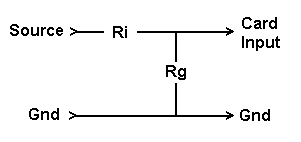
If the sound card had an infinite input impedance, the attenuation would be Rg / (Ri + Rg). With a real-world sound card, the input impedance appears in parallel with Rg and changes its effective value. If the sound card impedance is Rl, then the effective value is (Rg * Rc) / (Rg + Rc), which you could compute and plug into the voltage divider formula in place of Rg.
However, you typically don't know the actual input impedance, and you may not need to measure it at all. Apply the output of the sound card as the signal source to the attenuator, and connect one sound card input to the same spot, and one to the output of the attenuator (across Rg).
Toggle off the display of the Rg channel temporarily. Set the Generator to produce a sine wave at about 1 kHz and reduce the output volume or the Input range as needed so that the Spectrum shows only a single major peak (no clipping or other excessive distortion). Set both solid and dotted cursors to measure this same peak.
Toggle on the Rg channel and set its Input range to match the other. Click on one of the cursor channel selectors so that one cursor is reading each channel. With Spectrum Y-log toggled off, the ratio of the smaller over the larger peak value is the attenuation fraction. It takes into account the input impedance of the Rg channel; the other channel's impedance across the whole attenuator is not a factor here.
Note that since Daqarta takes care of the scaling factors, there is not much point in trying to get an exact attenuation factor like 0.5000 or 0.1000; Daqarta is just as happy with 0.4793 or 0.1152. However, one reason you might want a particular factor is if, for some reason, you need to frequently switch the attenuator in and out during testing and don't want to have to keep changing the External Gain setting. In that case a factor that you can apply in your head may be useful; for example, with a 10:1 ratio (0.1000) you can leave External Gain at unity and make a mental note that all values are 20 dB different when the attenuator is switched in.
Sometimes you may want an attenuator on the output signal. There are two typical reasons for this. One is to prevent overdriving the system under test. That system might be a sensitive device, such as a subject's ears listening to speakers or headphones. Even if you don't cause any damage, you could seriously compromise your subsequent results if you accidentally deliver a loud blast of sound while the subject is straining to hear very soft sounds in a threshold detection test. (And you may need to find a new subject, as well.)
Another reason is to reduce noise when you are only interested in low levels. Sound card outputs may have noise due to the intrinsic noise of their on-board circuitry, or due to picking up interference from other electronics inside the electrically-noisy computer case. If you are only trying to create very soft sounds (such as for the threshold detection test, above), adding an external attenuator can be very effective. For example, if the upper limit of your test signal is 40 dB below maximum output, then using a 40 dB (100:1) attenuator means the noise and interference is reduced by the same amount.
Ideally, the attenuator would go straight to the headphones to avoid any noise from a separate headphone amp. There is one potential pitfall with this, in that headphones (and speakers and many other devices) typically have an impedance that varies with frequency. Since the headphone is in parallel with the Rg resistor of the attenuator, the amount of attenuation can change with frequency.
The problem typically becomes worse the higher the value of the attenuator resistances. (To be specific, the higher the equivalent parallel combination of Ri and Rg, which is the effective impedance driving the headphones.) In addition to a more "peaky" frequency response, high driving resistance can cause the transient response to have increased ringing.
So you want Rg to be small relative to the nominal headphone impedance, which tends to make Ri smaller for any particular overall attenuation. But you don't want to make these so small that their total resistance is too small for the sound card output to drive. If the output is nornally meant to drive headphones, it can probably handle any load of 20 ohms or more. If it is a Line output, it may need to see more than 1000 ohms.
Macro Notes:
GainDlg=1 opens the External Gain dialog, GainDlg=0 closes it, and GainDlg=x toggles between open and closed.
Note that you do not need to open this dialog to change most of its controls directly via macro command, as long as they are enabled.
GainDlg?0 is a read-only variable that returns the current external gain setting for channel 0. You may use channels 0-3 here, given as a single digit. Alternatively, you can use V to specify the current Ch Channel Select number. A default gain value of 1.00 is returned for a channel number outside the 0-3 range, whether specified directly or via the V option.
    0 = Left In
    1 = Right In
    2 = Left Out
    3 = Right Out
    V = Ch value (0-3)
For input channels 0 or 1 the return value takes into account whether your sound card has separate input lines and if so which one is selected. Likewise, for output channels 2 or 3 it considers whether the sound card has separate Wave controls or uses only Master volume.
However, in each case the returned value is only the external gain setting; it does not include any attenuation or gain due to Input Line or Master levels, nor to output Wave or Master volume settings.
See Macro Data Unit Conversions for a discussion of how to use this variable together with others to obtain actual volts or User Units from ADC or DAC values returned by certain macro math and macro array functions.
To set or read specific lines in the External Gain dialog, use ExtGain0L for Left Input line 0 or ExtGain0R for Right, up to ExtGain7L and 7R. If your sound card does not have separate input range controls for each line, use ExtGainMstInL and R.
Use ExtGainWaveL and R for cards that have separate Wave controls, or ExtGainMstOutL and R if only Master volume is present.
- Back to Polarity Determination - Full-Scale Ranges
- Ahead to User Units Dialog
- Daqarta Help Contents
- Daqarta Help Index
- Daqarta Downloads
- Daqarta Home Page
- Purchase Daqarta
Questions? Comments? Contact us!
We respond to ALL inquiries, typically within 24 hrs.INTERSTELLAR RESEARCH:
Over 35 Years of Innovative Instrumentation
© Copyright 2007 - 2023 by Interstellar Research
All rights reserved