Software for Windows
Science with your Sound Card!


Features:
Oscilloscope
Spectrum Analyzer
8-Channel
Signal Generator
(Absolutely FREE!)
Spectrogram
Pitch Tracker
Pitch-to-MIDI
DaqMusiq Generator
(Free Music... Forever!)
Engine Simulator
LCR Meter
Remote Operation
DC Measurements
True RMS Voltmeter
Sound Level Meter
Frequency Counter
Period
Event
Spectral Event
Temperature
Pressure
MHz Frequencies
Data Logger
Waveform Averager
Histogram
Post-Stimulus Time
Histogram (PSTH)
THD Meter
IMD Meter
Precision Phase Meter
Pulse Meter
Macro System
Multi-Trace Arrays
Trigger Controls
Auto-Calibration
Spectral Peak Track
Spectrum Limit Testing
Direct-to-Disk Recording
Accessibility
Data Logger
Waveform Averager
Histogram
Post-Stimulus Time
Histogram (PSTH)
THD Meter
IMD Meter
Precision Phase Meter
Pulse Meter
Macro System
Multi-Trace Arrays
Trigger Controls
Auto-Calibration
Spectral Peak Track
Spectrum Limit Testing
Direct-to-Disk Recording
Accessibility
Applications:
Frequency response
Distortion measurement
Speech and music
Microphone calibration
Loudspeaker test
Auditory phenomena
Musical instrument tuning
Animal sound
Evoked potentials
Rotating machinery
Automotive
Product test
Contact us about
your application!
Daqarta Printed Circuits
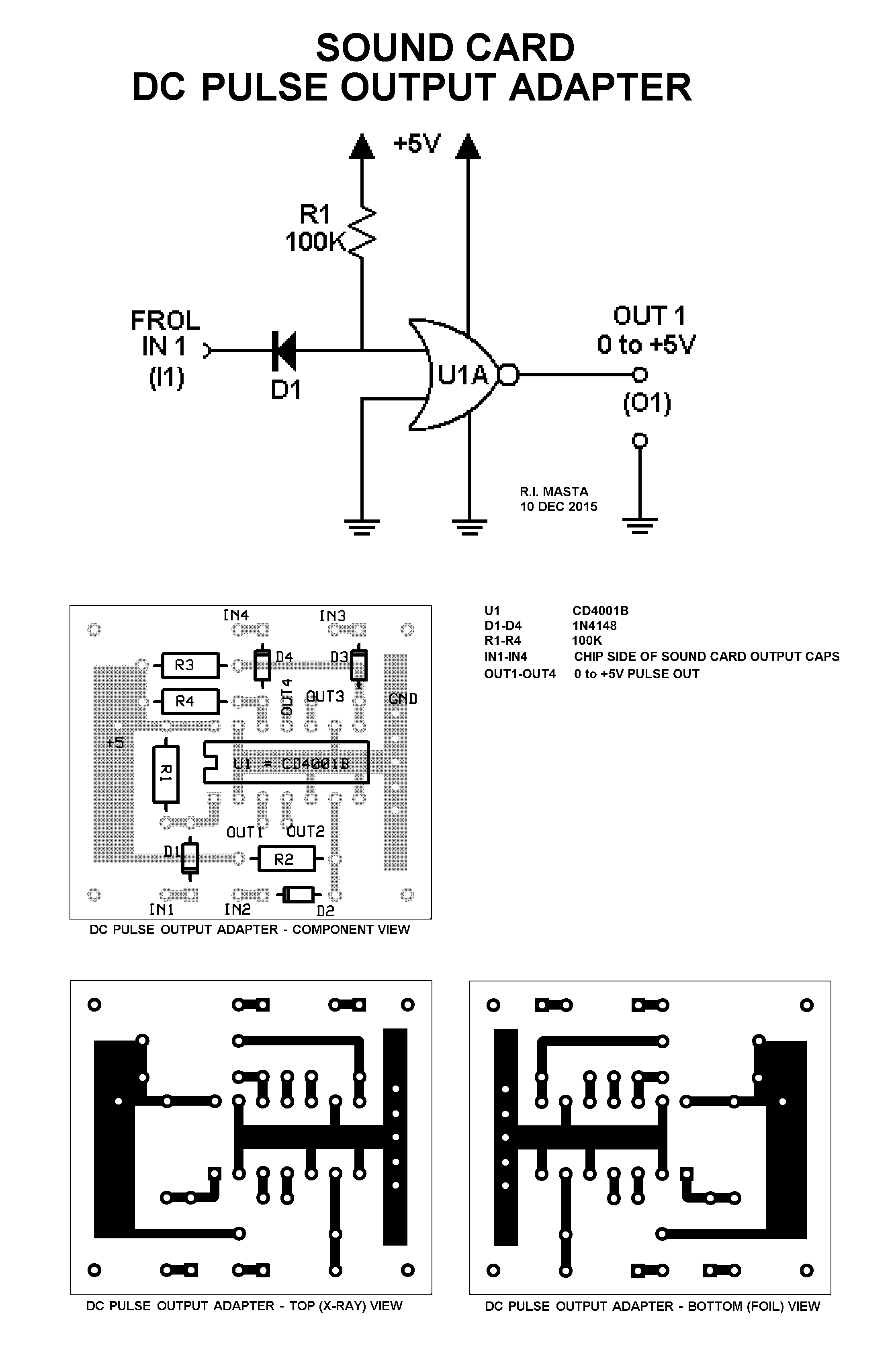
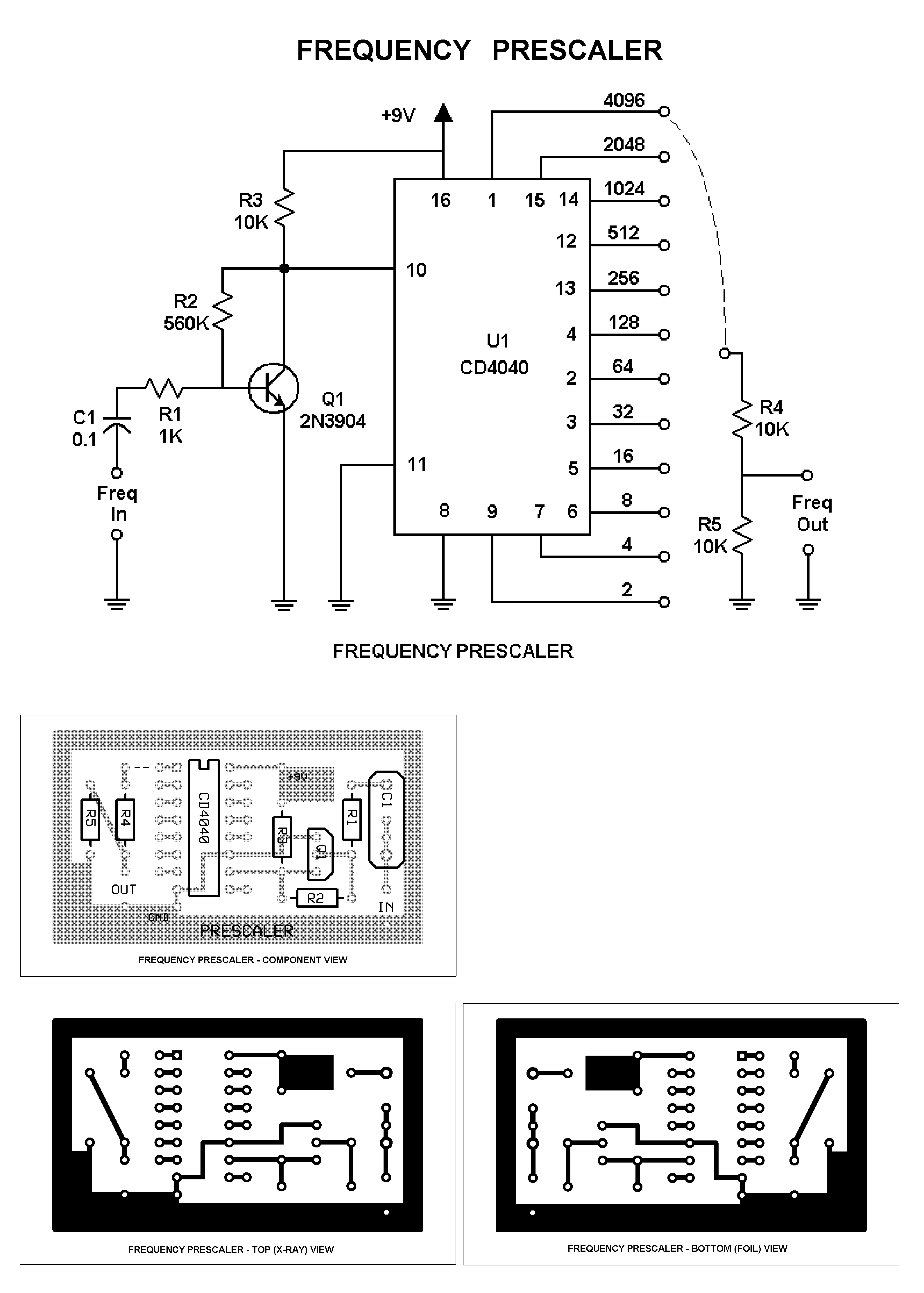
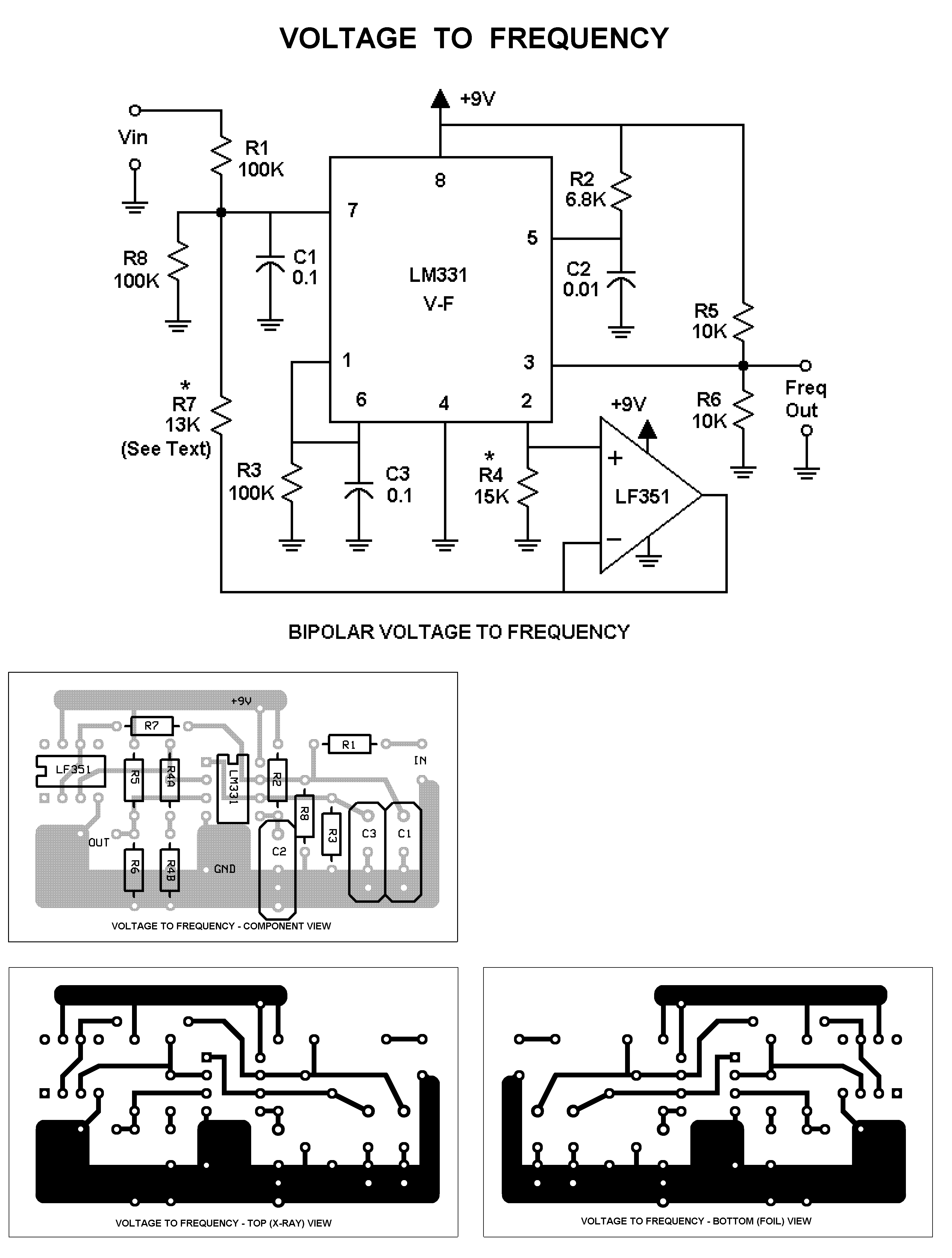
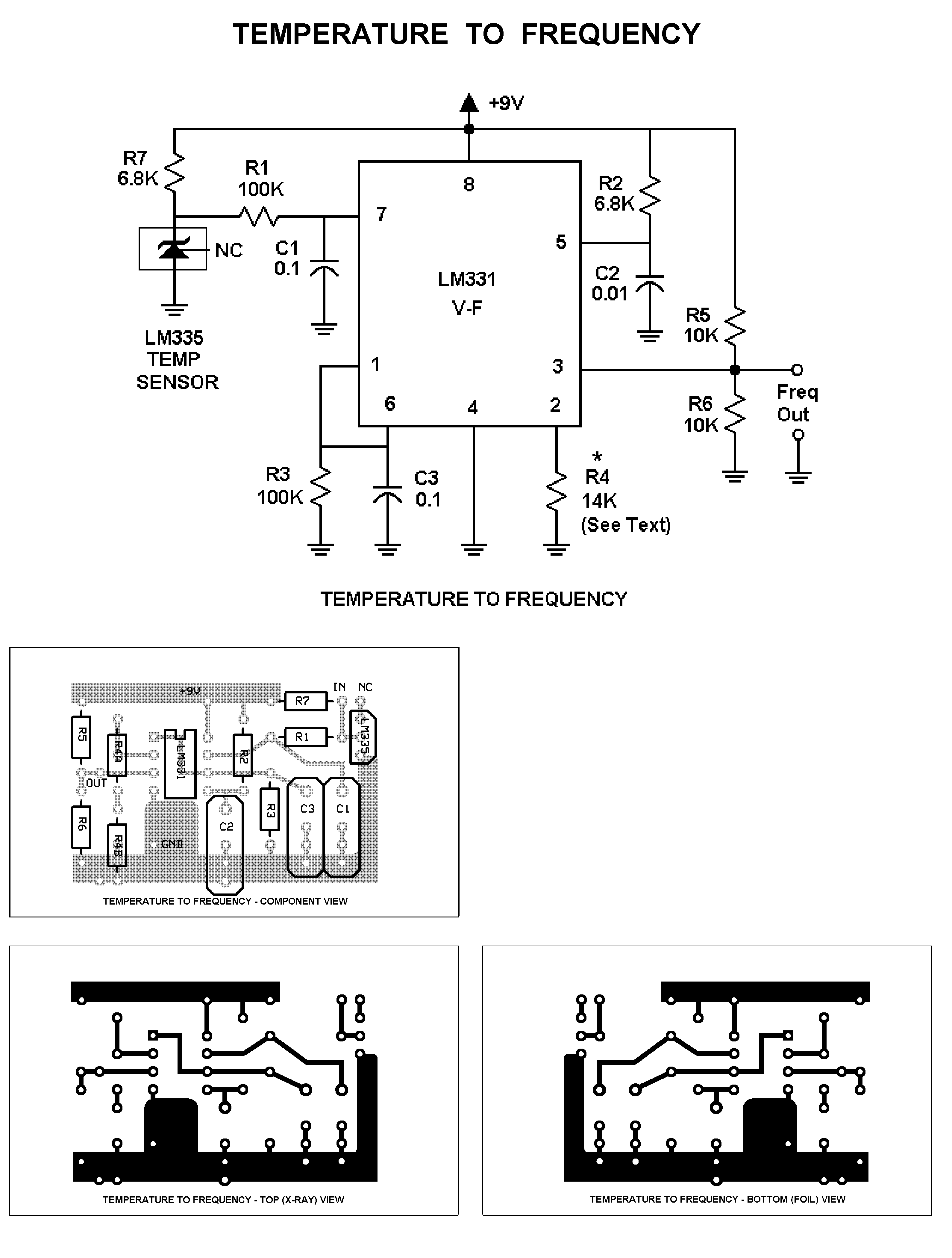
Daqarta includes a collection of supporting circuits in the Documents - Daqarta - Circuits folder.
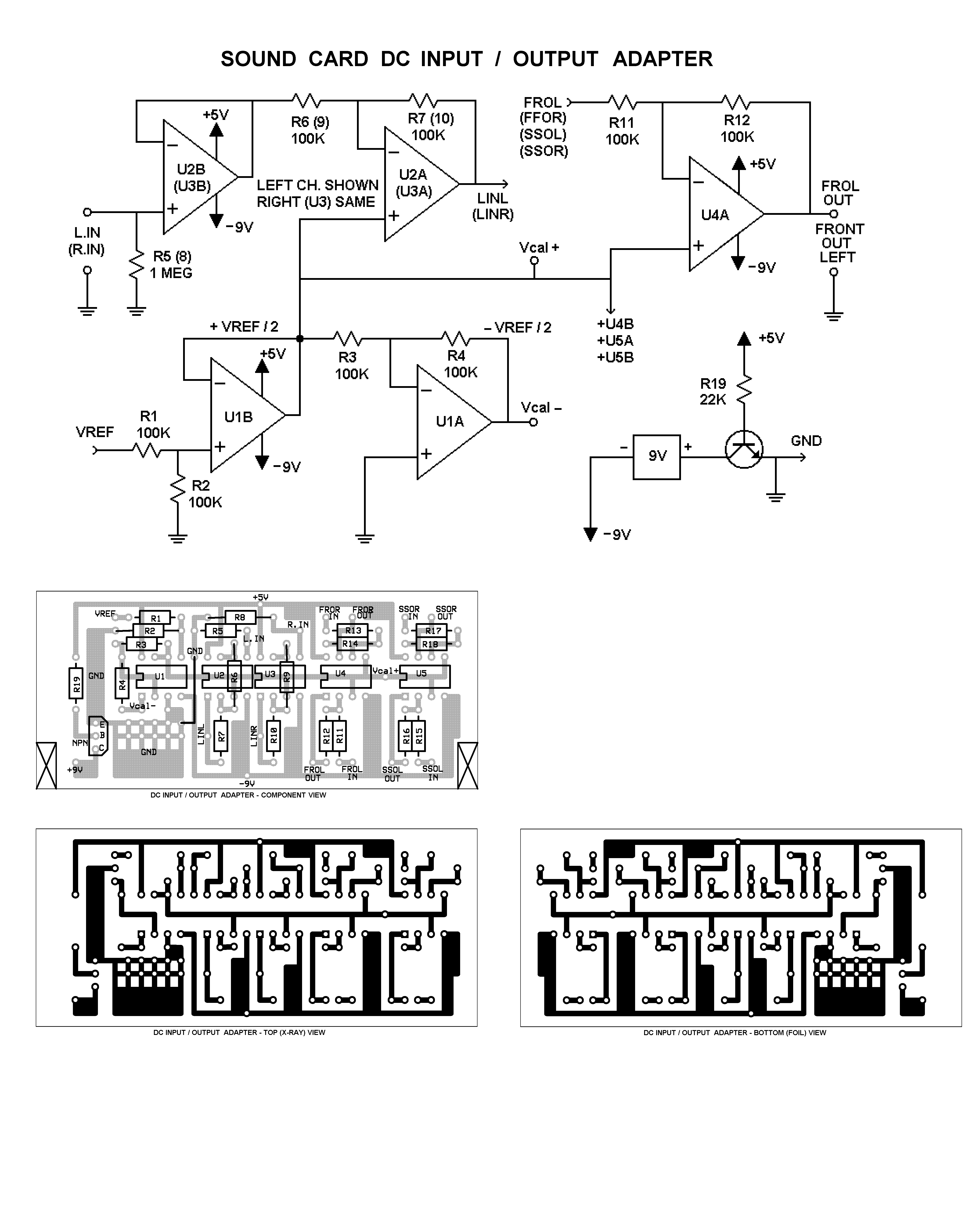
DC Measurement And Output circuits:
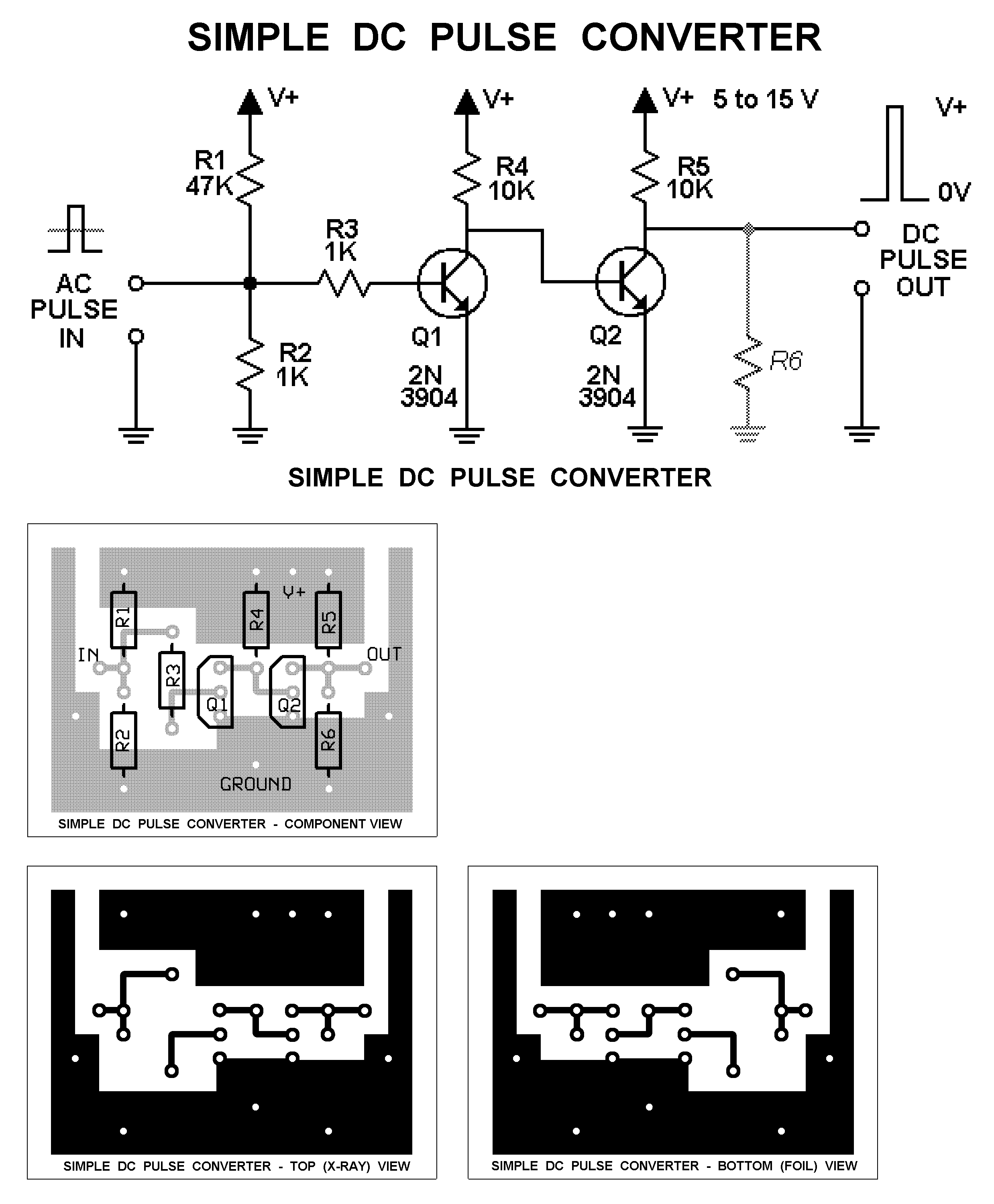
- Simple DC Pulse Converter
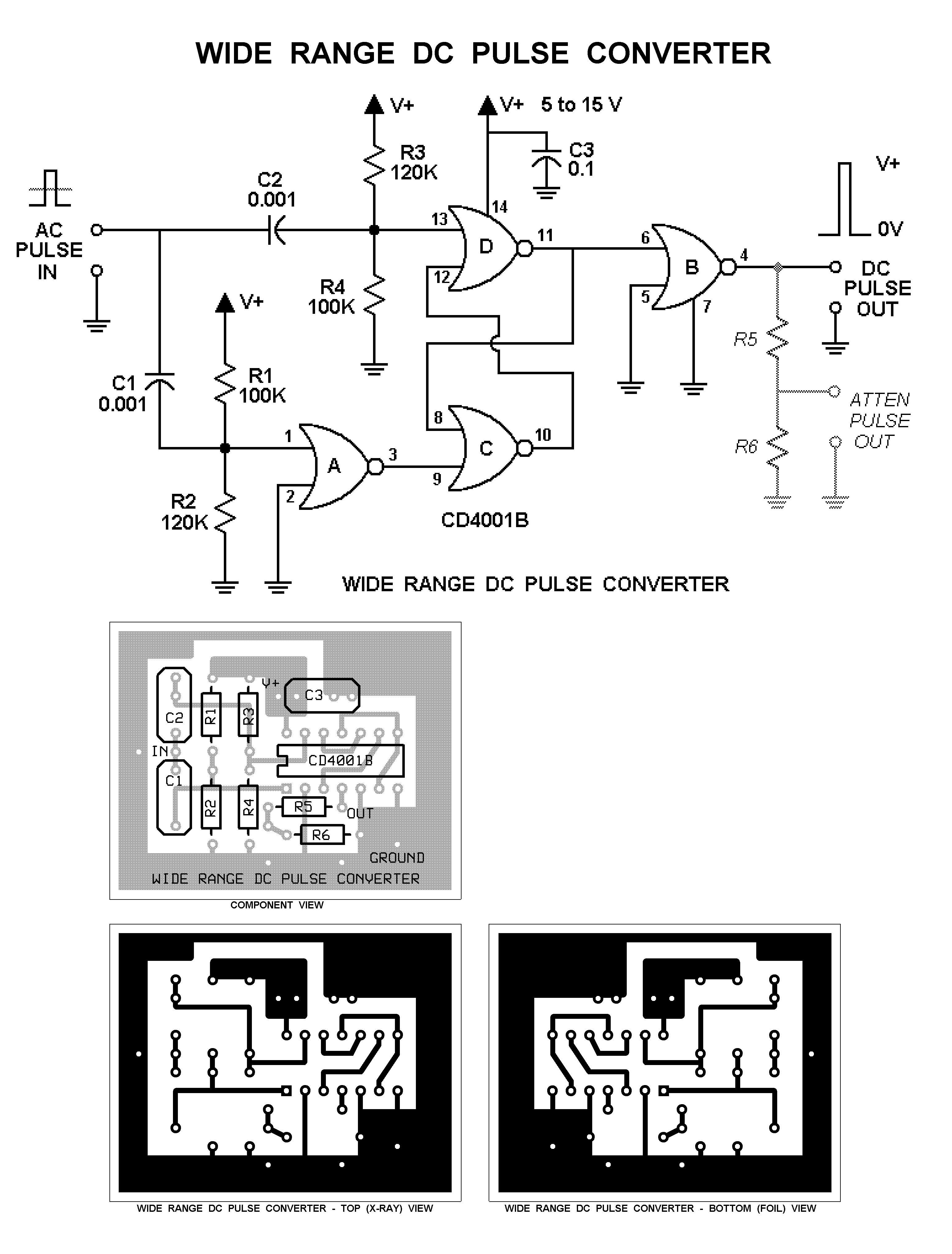
- Wide Range DC Pulse Converter
- LED Flasher / Modulator
- Low Frequency or Continuous DC Output
- Inexpensive All-In-One USB Device Modifications
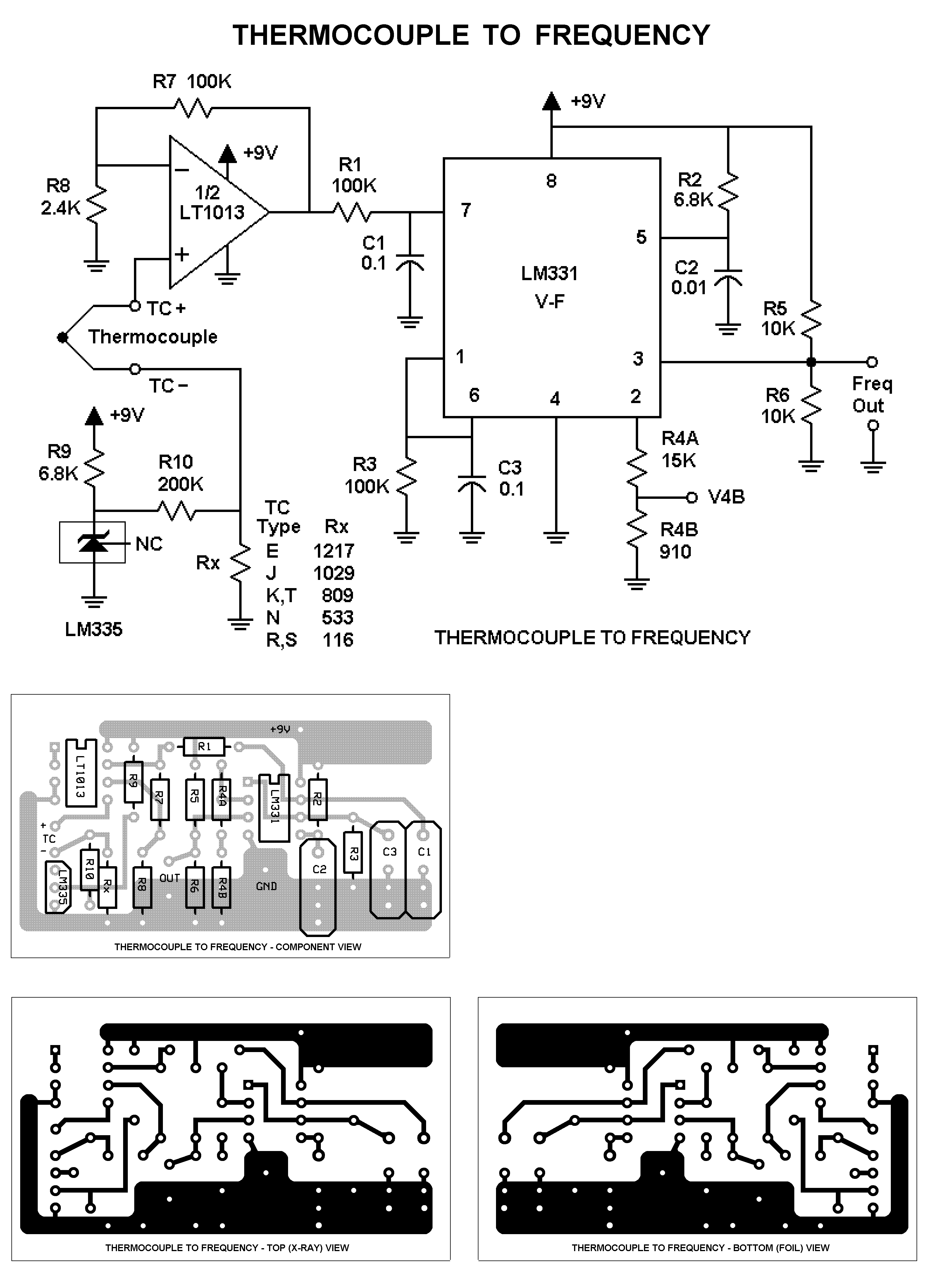
Frequency Counter Fcal circuits:
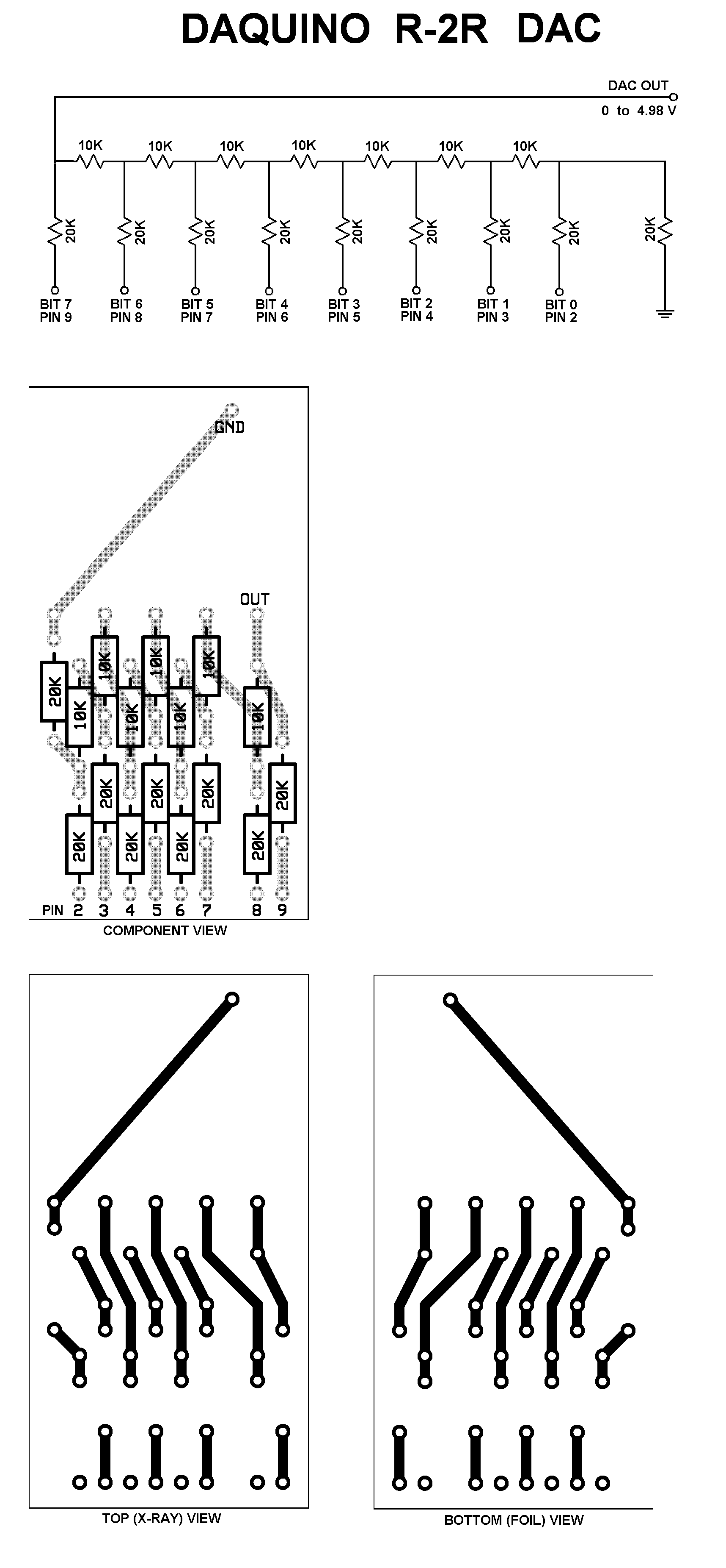
DaquinOscope Wavetable DAC circuit:
Notes:
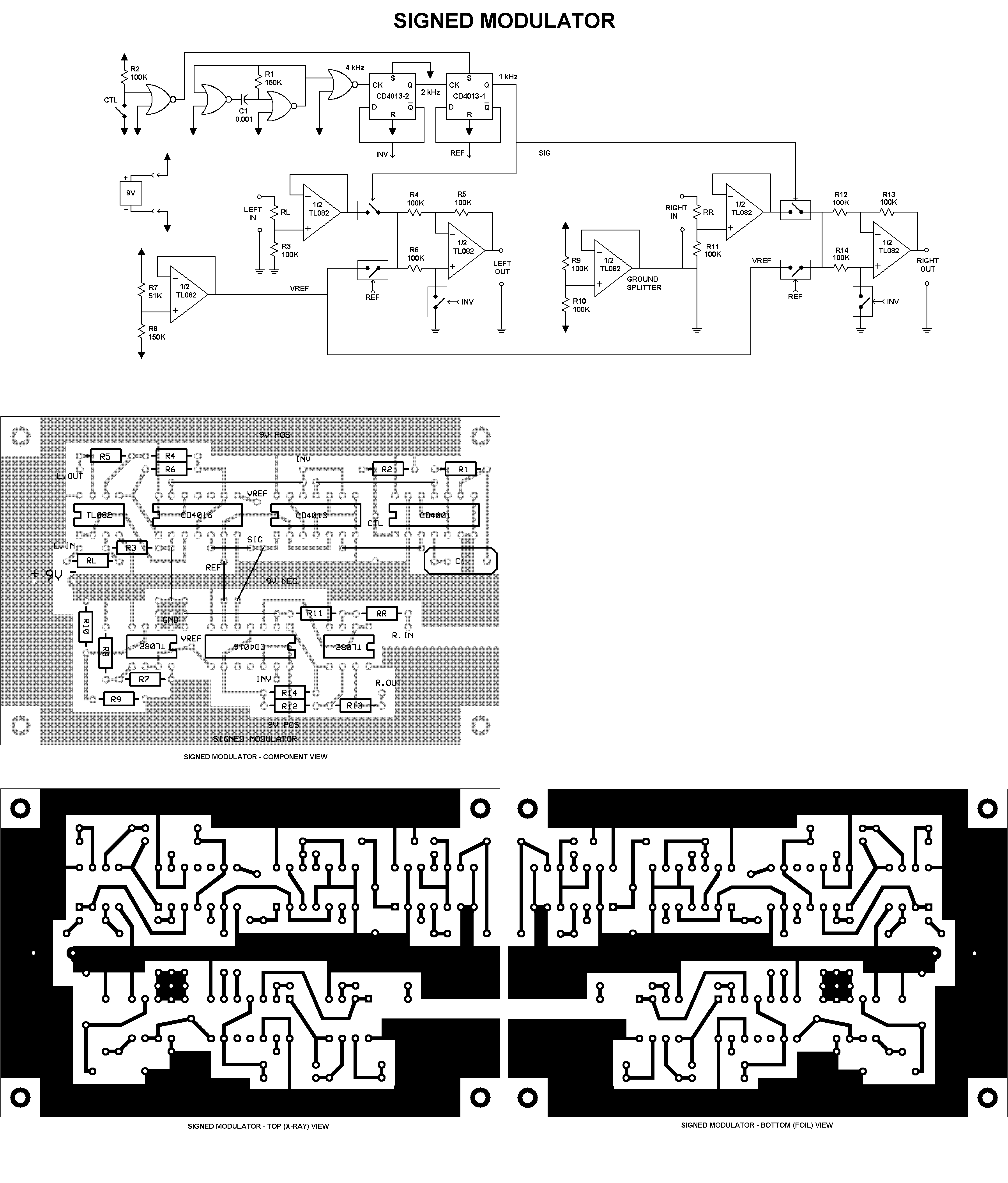
Each circuit (except the above DAC) has been designed to run from a single 9 V "transistor radio" battery. (See also 9 Volt Battery Connectors.) Standard, low-cost parts have been used throughout.
For each circuit, the folder includes a printable .PNG file with the schematic diagram and printed circuit board layouts at 600 DPI.
One way to print with this resolution is to open the .PNG file in Windows Paint. Then go to File - Print Preview and verify that things look OK. Paint will center the file image in the page, but will maintain the DPI setting. Click Print, select printer, and print it.
Do not just click on the image from Windows Explorer, since the default app to open the image will be the Windows Media Viewer, which will not necessarily respect the DPI setting, even if you unselect "Adjust to fit page".
All boards are simple single-sided boards, and can be fabricated by copying the layout to transfer paper using a laser printer, then ironing it onto copper-clad circuit board and etching, drilling, and soldering the components. There are many Websites that explain this method... search for "PCB toner transfer".
Note: The laser printer iron-on method uses the left board layout, marked "TOP (X-RAY) VIEW". This will give the correct result when the printed image is ironed onto the bottom (foil) side of the board.)
You can also create these simple boards by drawing directly onto the copper-clad board with an indelible felt-tip marker, instead of the laser printer transfer method. See Printed Circuit Construction for full details. That topic also includes important drilling and etching tips that will apply even if you use the toner transfer method.
The .PNG file has both top ("X-ray") and bottom views of the copper foil pattern, as well as a top view showing the component placement over the X-ray foil traces in light gray.
PCB Files:
If you want to have boards made professionally, the Circuits folder also includes a .PCB file for each circuit. These were created by the ExpressPCB program, which is available free from the company of the same name at www.expresspcb.com . You can load these files into ExpressPCB and edit them as desired, then upload to the company to have the boards made.
Daqarta is not affiliated with ExpressPCB in any way. These ExpressPCB files are provided strictly as a convenience for users.
Please note that some of the Daqarta circuit layouts are smaller than the economy ExpressPCB MiniBoard Service standard of 3.8 by 2.5 inches, which means you would actually pay more for the smaller size. To avoid this, you can use the ExpressPCB software to edit the board outline just by dragging the corners to the standard size. (Note that a MiniBoard order must always be for 3 identical boards. The total cost of the order as of late 2010 is US $60.85, including shipping within the US.)
Alternatively, you can combine two different PCB files into one layout at the MiniBoard size, or (if you need a lot of the same board) put two copies of the same circuit on one board.
In fact, most Daqarta circuits include blank space around the margins, so you may be able to squeeze three circuits into the MiniBoard footprint if you don't require the margin space for mounting holes, etc.
If you want to make your own boards, but with custom modifications for your own particular needs, you can edit the .PCB files with ExpressPCB and print them directly from the program. The printed images will only be 300 DPI, but that is adequate for most toner transfer use. The reduced resolution has no effect on hand-drawn boards, since the printed images are only used to mark drill holes and to use as a drawing guide.
- Back to Isolation, Electrical
- Ahead to Printed Circuit Construction
- Daqarta Help Contents
- Daqarta Help Index
- Daqarta Downloads
- Daqarta Home Page
- Purchase Daqarta
Questions? Comments? Contact us!
We respond to ALL inquiries, typically within 24 hrs.INTERSTELLAR RESEARCH:
Over 35 Years of Innovative Instrumentation
© Copyright 2007 - 2023 by Interstellar Research
All rights reserved