Software for Windows
Science with your Sound Card!


Features:
Oscilloscope
Spectrum Analyzer
8-Channel
Signal Generator
(Absolutely FREE!)
Spectrogram
Pitch Tracker
Pitch-to-MIDI
DaqMusiq Generator
(Free Music... Forever!)
Engine Simulator
LCR Meter
Remote Operation
DC Measurements
True RMS Voltmeter
Sound Level Meter
Frequency Counter
Period
Event
Spectral Event
Temperature
Pressure
MHz Frequencies
Data Logger
Waveform Averager
Histogram
Post-Stimulus Time
Histogram (PSTH)
THD Meter
IMD Meter
Precision Phase Meter
Pulse Meter
Macro System
Multi-Trace Arrays
Trigger Controls
Auto-Calibration
Spectral Peak Track
Spectrum Limit Testing
Direct-to-Disk Recording
Accessibility
Data Logger
Waveform Averager
Histogram
Post-Stimulus Time
Histogram (PSTH)
THD Meter
IMD Meter
Precision Phase Meter
Pulse Meter
Macro System
Multi-Trace Arrays
Trigger Controls
Auto-Calibration
Spectral Peak Track
Spectrum Limit Testing
Direct-to-Disk Recording
Accessibility
Applications:
Frequency response
Distortion measurement
Speech and music
Microphone calibration
Loudspeaker test
Auditory phenomena
Musical instrument tuning
Animal sound
Evoked potentials
Rotating machinery
Automotive
Product test
Contact us about
your application!
Voltage Dividers
A simple 2-resistor voltage divider can function as a fixed attenuator to reduce a signal level that is too large.
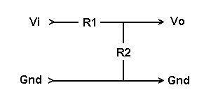
Given the input voltage Vi and the two resistors R1 and R2, the output voltage Vo is:
Vo = Vi * R2 / (R1 + R2)
The fractional voltage reduction K is:
K = Vo / Vi = R2 / (R1 + R2)
To get a specified output voltage from a known input voltage, pick one of the resistor values and solve for the other:
R2 = Vo * R1 / (Vi - Vo)
R1 = R2 * (Vi - Vo) / Vo
Or, if you know the desired fraction K and want to find the resistors:
R2 = K * R1 / (1 - K)
R1 = R2 * (1 - K) / K
The ratio of the two resistors needed for a given reduction is:
R2/R1 = K / (1 - K)
R2/R1 = Vo / (Vi - Vo)
To determine the input voltage that produces a given output voltage from a known divider:
Vi = Vo * (R1 + R2) / R2
The reduction ratio K is normally used for range changes, such as 0.10 for a 10-to-1 reduction. However, for audio work you may want to obtain a specific reduction in dB. (See dB From Voltages and Working With dB.)
The dB corresponding to a given voltage ratio is:
dB = 20 * log10(Vo / Vi)
dB = 20 * log10(K)
where log is the base-10 (common) logarithm. For voltage dividers, note that K is always less than 1, so the dB value will always be negative.
To find the ratio K corresponding to a given dB value, use the following formula. Remember to use a negative value for dB:
K = 10^(dB/20)
Typical dB values and corresponding voltage ratios:
-1 = 0.891251
-2 = 0.794328
-3 = 0.707946
-6 = 0.501187
-10 = 0.316228
-20 = 0.100000
-30 = 0.031623
-40 = 0.010000
-60 = 0.001000
-80 = 0.000100
-100 = 0.000010
-120 = 0.000001
- Back to Trigonometric Relationships
- Ahead to List Of Included Daqarta Files
- Daqarta Help Contents
- Daqarta Help Index
- Daqarta Downloads
- Daqarta Home Page
- Purchase Daqarta
Questions? Comments? Contact us!
We respond to ALL inquiries, typically within 24 hrs.INTERSTELLAR RESEARCH:
Over 35 Years of Innovative Instrumentation
© Copyright 2007 - 2023 by Interstellar Research
All rights reserved