Software for Windows
Science with your Sound Card!


Features:
Oscilloscope
Spectrum Analyzer
8-Channel
Signal Generator
(Absolutely FREE!)
Spectrogram
Pitch Tracker
Pitch-to-MIDI
DaqMusiq Generator
(Free Music... Forever!)
Engine Simulator
LCR Meter
Remote Operation
DC Measurements
True RMS Voltmeter
Sound Level Meter
Frequency Counter
Period
Event
Spectral Event
Temperature
Pressure
MHz Frequencies
Data Logger
Waveform Averager
Histogram
Post-Stimulus Time
Histogram (PSTH)
THD Meter
IMD Meter
Precision Phase Meter
Pulse Meter
Macro System
Multi-Trace Arrays
Trigger Controls
Auto-Calibration
Spectral Peak Track
Spectrum Limit Testing
Direct-to-Disk Recording
Accessibility
Data Logger
Waveform Averager
Histogram
Post-Stimulus Time
Histogram (PSTH)
THD Meter
IMD Meter
Precision Phase Meter
Pulse Meter
Macro System
Multi-Trace Arrays
Trigger Controls
Auto-Calibration
Spectral Peak Track
Spectrum Limit Testing
Direct-to-Disk Recording
Accessibility
Applications:
Frequency response
Distortion measurement
Speech and music
Microphone calibration
Loudspeaker test
Auditory phenomena
Musical instrument tuning
Animal sound
Evoked potentials
Rotating machinery
Automotive
Product test
Contact us about
your application!
DC Chart Recorder Mini-App
- Introduction
- Operation
- Simultaneous Sound Card Operation
- Variable, Control, and Array Usage
- DC_Chart_Recorder Macro Listing
- _DC_Chart_Ctrls Macro Subroutine Listing
- _DC_Chart_Chans Macro Subroutine Listing
- _DC_Chart_Task Macro Subroutine Listing
- _DC_Chart_Arduino Macro Subroutine Listing
- _DC_Chart_Numato08 Macro Subroutine Listing
- _DC_Chart_Numato16 Macro Subroutine Listing
- _DC_Chart_Numato32 Macro Subroutine Listing
- _DC_Chart_Numato64 Macro Subroutine Listing
- _DC_Chart_Write Macro Subroutine Listing
Introduction:
The DC_Chart_Recorder macro mini-app is included with Daqarta. It records 1, 2, 4, or 8 simultaneous channels of analog or digital data using an Arduino Uno or Numato USB GPIO device. Data is acquired from the device via its USB virtual serial port and shown on the screen as a scrolling display, and optionally saved to a binary file (.DQA, which is Daqarta's extended .WAV format) or logged to a text file, or both. The .DQA file may be opened later by Daqarta for review and analysis. The log file is in standard .TXT format which may be opened by any text editor (such as Windows Notepad), or converted by most spreadheet software.
Chart speed may be selected from 0.01 seconds per sample to 1 hour per sample in 19 steps. An input voltage range control allows you to calibrate the recorder to compensate for any external gain or attenuation used.
Supported devices are:
    Arduino Uno (and compatible) running DaqPort
    Numato GPIO 8
    Numato GPIO 16
    Numato GPIO 32
    Numato GPIO 64
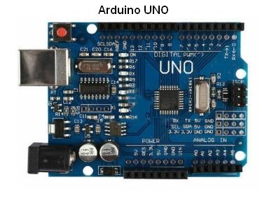
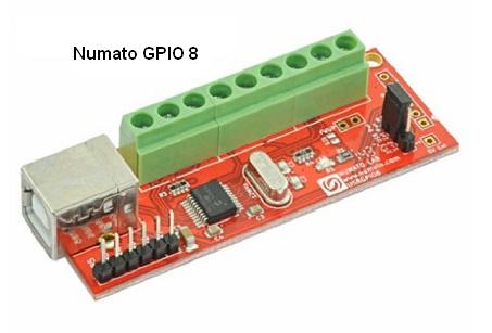
Unlike sound cards, all of these devices are DC-coupled. The Arduino and Numato GPIO 8 use a 0-5.0 V range, while the others use 0-3.3 V. The analog inputs use 10 bits to cover the range, returning values from 0 to 1023 which are scaled to report 0 to 1023/1024 of the range.
(Note that you can use the simple AC-to-DC Input Level Shifter and Limiter circuit to shift AC signals in the +/-2.5 V range up to 0-5 V for recording here, as needed.)
To run the DC_Chart_Recorder, hit the F8 key followed by the unshifted r key. Note that this macro ID is case-sensitive because the Chart Recorder macro uses an uppercase R as its ID.
Alternatively, hit CTRL+F8 to open the Macro Dialog and double-click on DC_Chart_Recorder in the Macro List. Or hit the unshifted r key twice to move to that list item, then hit the Enter key.
Note: Since the DC_Chart_Recorder doesn't use the sound card inputs, you don't need a Daqarta license to use it after the trial period... it's absolutely free, forever!
(However, if you modify the macro code after the trial period, and want to save the changes for future sessions, you need a Professional license.)
Operation:
The DC_Chart_Recorder uses a Custom Controls dialog that allows adjustment of various parameters. You can open this Help topic by right-clicking anywhere in the dialog. (You can also open it by clicking on the Help button when DC_Chart_Recorder is selected in the Macro List, or in the Macro Edit dialog.)
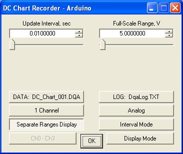
Chart Speed (Update Interval):
Ctrl0 is the Update Interval between time points. As the above image shows, DC_Chart_Recorder starts running at maximum speed (Update Interval = 0.01 sec). Note that at the 3 fastest speeds (Update Intervals of 0.01, 0.02, and 0.05 seconds) the actual speed on many systems may be slower than the nominal value. In this case the value displayed on the control, and the equivalent X-axis time calibration, will change every second for about 10 seconds while homing in on the actual value.
Note also that setting the Trace Update Interval (in the X-Axis control dialog) higher than the default of 10 msec may slow DC_Chart_Recorder speeds, and in some cases a lower setting may improve the fastest speeds. If you want to experiment with this, please note that the auto-adjust in DC_Chart_Recorder is initiated by changing its Update Interval (or other speed-related control like number of channels); if you change the X-Axis Trace Update Interval you must make a dummy change to the DC_Chart_Recorder for the auto-adjust to take effect. (Set the Update Interval up and back down to the step you wanted, for example.)
The default Update Interval is set by the UR=0 line near the start of the DC_Chart_Recorder macro. You can set a preferred default by changing the value for UR:
     0     0.01 sec
     1     0.02
     2     0.05
     3     0.1
     4     0.2
     5     0.5
     6     1
     7     2
     8     5
     9     10
    10     20
    11     30       (0.5 min)
    12     60       (1 min)
    13     120      (2 min)
    14     300      (5 min)
    15     600      (10 min)
    16     1200     (20 min)
    17     3000     (50 min)
    18     3600     (1 hour)
Note, however, that if your preferred Update Interval is large, the resultant slow display updates may make it harder to tell if everything is working properly when DC_Chart_Recorder is started. In such cases it may be better to start with a high default speed (short interval) and change it after verifying that signals look OK.
Full-Scale Range:
Ctrl1 is the Full-Scale Range for the analog inputs. By default, it is set to the intrinsic range of the device in use, which also happens to be its digital input "high" value. In the image above the device is an Arduino, as shown in the title bar, so the default is 5.00 V. If you use an external amplifier or attenuator you can set this value to compensate.
For example, if you apply an attenuation of 10:1 ahead of the analog input, the attenuator input would need to be 50 V for the Arduino to see 5 V, so you would set the Full-Scale Range value to 50. Conversely, if you used a preamplifier with a gain of x10, its input would only be 0.5 V for the Arduino to see 5 V, so you'd set the Full-Scale Range to 0.5.
The value you set here is assumed to apply to all input channels. It is used to set the vertical axis of the main Daqarta display, and also the cursor readouts if you are using Process Mode instead of the default Display Mode. (See below.)
If you have a fixed gain or attenuation that you want this control to incorporate by default, you can set it by modifying a value near the start of the DC_Chart_Recorder macro. Arduino and Numato GPIO 8 devices use the F=5.00 default, while all other Numato devices use the G=3.30 default.
DATA File Recording:
Btn0 in the above image shows "DATA: DC_Chart.DQA". This button toggles binary data recording to a .DQA file using the default name shown.
.DQA is Daqarta's extended .WAV format. Advantages include the preservation of X and Y calibration data that Daqarta can use to show the original voltages and times on subsequent viewing of the file, along with any Notes that were made at the time of the recording.
You can change the default file by changing the quoted string in the Str1="DC_Chart" line near the start of the DC_Chart_Recorder macro code. Note that the software will automatically add the .DQA extension itself.
If you use software other than Daqarta to view these files, you will need to manually change the extension from .DQA to .WAV after the recording. (You can't force direct save to .WAV without deeper changes to the macro code. Contact us if you really want to do that.)
Once DC_Chart_Recorder is running, you can change the file name whenever the button is enabled. (It is disabled whenever recording is in progress.) To do this, hold down the CTRL key while clicking the button; you will be prompted to enter the desired name, which will then replace the old one on the button. Recording will not start until you click the button again without the CTRL key. You can use this feature repeatedly during a session as you change subjects or items under test.
You can toggle recording on and off as needed throughout the session while keeping the same file name, such as to stop recording during times of obvious outside interference, or when making adjustments. The name will only change when you use the CTRL key with the click.
If you want the file names to form an ever-increasing series, such as Rat000, Rat001, etc., you can go to the main Daqarta File menu and toggle "Auto-Increment Filenames" on (a check mark will appear at the left). You can toggle this on or off any time while the DC_Chart_Recorder is running.
Alternatively, you can modify the DC_Chart_Recorder macro code to always auto-increment, regardless of the main File menu Auto-Increment state, or to never auto-increment. Locate this line near the start of the code:
UF=2 ;Auto-increment DATA file name
Change the value of UF as needed:
UF=0       ;Never auto-increment
UF=1       ;Always auto-increment
UF=2       ;Use main Auto-Increment state
Note that even with auto-increment active, you will still need to use CTRL+Click to change the filename. The difference is that the default Save As name will show the next increment, so you can simply accept it as-is.
In some cases you may want to set the LOG file (see the next section) to the same base name. Instead of holding down CTRL to change the DATA name, just hold down SHIFT set both via the same operation. If you are using auto-increment on the DATA name, note that the current increment will appear on the LOG name as well. Auto-increment is otherwise never applied to LOG names.
LOG File Recording:
Btn1 in the above image shows "LOG: DqaLog.TXT". This button toggles data logging to an ordinary ASCII text file using the default name shown. This is the standard Daqarta default name for all logging operations. You can change the default file by changing the quoted string in the A.LogName="DqaLog" line near the start of the DC_Chart_Recorder macro code. Note that the software will automatically add the .TXT extension itself.
As with DATA recording (see above), once DC_Chart_Recorder is running you can change the log file name whenever this button is enabled. (It is disabled whenever recording is in progress.) To do this, hold down the CTRL key while clicking the button; you will be prompted to enter the desired name, which will then replace the old one on the button. Logging will not start until you click the button again without the CTRL key. You can use this feature repeatedly during a session as you change subjects or items under test.
When you toggle this button on to begin logging, a header line is sent to the file. A typical header looks like this:
8/26/2018 Arduino 0.010 sec/smpl Analog 5.000 Vfs
The first entry is the date, which uses the Date Format chosen via Date/Time Preferences in the Edit menu.
Next is the device name (Arduino, Numato08, Numato16, Numato32, or Numato64), followed by the current chart Update Interval. The Btn3 Analog/Digital input state (see later) is next, followed by the Full-Scale Range.
Each log entry begins with the time (in the Time Format selected in Date/Time Preferences), followed by entries for each active channel (see below). Here's an example for 4 channels:
10:22:11.750     1.558   1.719   1.548   1.821
10:22:11.765     1.826   1.826   1.812   1.567
10:22:11.781     1.538   1.606   1.621   1.777
You may notice that the times do not progress by steps of the selected 0.010 sec/sample indicated in the header. In this example the system wasn't fast enough for that, and the actual Update Interval showed just under 0.016 sec after automatic self-calibration. Nevertheless, the header shows the nominal value that you originally set, which is also what you would set if you wanted to repeat the test.
The log is a standard text file that can be opened by any text editor, such as Windows Notepad. Other software may allow setting up a template to read the relevant fields from a text file into spreadsheet columns or database entries. If you create such a template, don't forget to deal with the header. This is of special concern if you will be toggling the logging operation off and back on during the test (such as while waiting for background noise to subside, or for adjustments to the part under test, or for the subject to stop squirming). It may also be a problem if you are using the ALT-Click option below to save Notes to the log file.
The above DATA File Recording subtopic discussed use of Auto-Increment on DATA file names. This option is not directly available for LOG files, only indirectly by using SHIFT+Click on the DATA name to make the LOG name the same. If you want independent auto-increment for the LOG name, you'll need to modify the code as noted in the Auto-Increment Help topic.
Saving Notes to the Log File:
If you hold down the ALT key while clicking the LOG button, the contents of Notes will be sent to the log file. The format is:
14:42:36.593 Notes content here
A new line will be started with a 3-space indent, followed by the time (with the same Time Format as the log itself), another 3 spaces, then the entire Notes content. The indent is not only to make the Notes line stand out from the rest of the log, but also to allow spreadsheet or database file conversion templates to detect that this is not a data line. However, please note that Notes accepts multiple lines. If the original Notes consists of:
Notes line 1
Notes line 2
Notes line 3
Then the resulting log entry will be of the form:
   16:34:55.328   Notes line 1
Notes line 2
Note line 3
Thus, if your template is using the indent to detect non-data lines, you must either avoid multiple lines, or manually insert spaces at the start of subsequent lines. Alternatively, if you simply enter a single very long line without using the Enter key, the Notes editor will wrap it automatically to fit the display area. This will not be wrapped in the log file, so your template can still use the indent for non-data detection.
An important feature of the ALT+Click option is that it works even if normal data logging isn't active (Btn1 up). This allows you to save Notes to the log file during DATA recording. The time-stamp ahead of the Notes line allows you to relate the entry to times in the data (.DQA) file.
In order to do that, after you later open the data file you must click on the DDisk Position readout below the right end of the trace area (or hit ALT+SHIFT+D) as needed to get it to show Local time (or UTC if you've chosen that via the Time Format control in Date/Time Preferences). The DDisk Position will then show the time at the start of the screen. Toggle Cursor Units on at the bottom of the DDisk control dialog (or hit ALT+SHIFT+D) and the X-position cursor readouts will show a pink background to indicate that they also are in the same time units and are likewise relative to the start of the file instead of the normal start of the display frame.
Now you can enter the saved time into DDisk Position to jump to that time in the file. (You can use manual entry, or copy and paste from the log file.) You can move the file position backwards a little to see what happened just before that time, if needed. If other events are on the same screen, you can just move a cursor until its X position readout shows the corresponding time.
Number Of Channels:
Btn2 defaults to "1 Channel". Successive clicks advance to 2, 4, and 8 channels then wrap back to 1. You can move in the reverse direction by holding down the SHIFT key while clicking.
See the 8-Channel Subset topic for Btn6 (below) for additional information on using 8 channels.
When 1 channel is selected it is always channel 0, then 0 and 1 for 2 channels, 0-3 for 4 channels, and 0-7 for 8. However, most devices have less than 8 ADC channels, so when the Analog / Digital button (Btn3) is in Analog mode, certain digital channels are substituted.
Arduino: The marked Analog inputs A0-A5 are used for analog channels 0-5, but Digital pins 8 and 9 are used for analog channels 6 and 7. In Digital mode, pins 2-9 are read as channels 0-7.
Numato: The four supported Numato USB GPIO (General Purpose Input / Output) devices use the same pins for analog inputs as for digital I/O. Each device maps them a little differently, however. The DC_Chart_Recorder uses a unified scheme, whereby the IO pin number is also used as the analog channel number. In the table below, -NA- means that there is no analog input for that pin, so the corresponding digital input is used instead.
Note that in the case of the Numato 8, this scheme results in pins IO4 and IO5 being used in digital input mode for "Analog" channels 4 and 5, whereas pins IO6 and IO7 are used as channels 6 and 7 but are really Numato ADC4 and ADC5.
In Digital mode, the channel numbers match the pin numbers for all Numato devices.
    DC_Chart   ----------- Numato pin maps ------------
    Recorder   GPIO   Numato   Numato   Numato   Numato
    Channel    Pin      8        16       32       64
       0       IO0     ADC0     ADC0     -NA-     ADC0
       1       IO1     ADC1     ADC1     ADC1     ADC1
       2       IO2     ADC2     ADC2     ADC2     ADC2
       3       IO3     ADC3     ADC3     ADC3     ADC3
       4       IO4     -NA-     ADC4     ADC4     ADC4
       5       IO5     -NA-     ADC5     ADC5     ADC5
       6       IO6     ADC4     ADC6     ADC6     ADC6
       7       IO7     ADC5     -NA-     ADC7     ADC7
Analog / Digital Recording:
Btn3 defaults to "Analog", to record from the ADC inputs specified by the Channels control (see above). The recorded and displayed values are scaled according to the Full-Scale Range control (Ctrl1, above). The ADCs are used in 10-bit mode, such that their maximum output value of 1023 counts is equal to 1023/1024 of Full-Scale Range.
Toggling to "Digital" records from the digital I/O inputs specified by the Channels control. The recorded and displayed values are arbitrarily scaled such that a digital high is shown as 1000 counts, not the 1024 counts equivalent to Full-Scale Range. This is to allow easy reading of multi-channel displays in Separate Ranges Display mode (see below), where the highs of one channel could otherwise be hard to distinguish from the lows of the one above it. (This is usually not a problem with analog signals, unless you are monitoring full-scale square waves.)
However, the Log file does not apply this 1000 scaling, and shows the digital values as 0.000 or 1.000.
Separate / Shared Ranges:
Btn4 defaults to "Separate Ranges Display" (button depressed), which means that when multiple channels are displayed they are reduced in size on the screen and stacked so the traces don't overlap.
For example, if Full-Scale Range is set to 5.00 volts and only 1 channel is shown, it uses the whole vertical range of the screen and the Y axis shows 0 at the bottom and 5000 mV at the top. With 2 channels each uses half the vertical range, and the Y axis shows 0 at the bottom and 10 V at the top. The top channel (Channel 0) appears to run from 5 to 10 V, while the bottom channel (Channel 1) is properly shown between 0 and 5 V. With 4 channels the Y axis runs to 20 V, and with 8 it runs to 40 V.
When the button is toggled to "Shared Ranges Display" all traces share the same screen space (unless Btn7 is toggled to Process Mode instead of Display Mode... see below.) This gives best screen resolution of fine details, but is only feasible if there isn't too much natural overlap between traces. Note that this has no effect on recorded DATA file or LOG file data, so you can toggle back and forth at will.
Interval / Time Mode:
Btn5 defaults to Interval Mode, where the first time point is taken immediately after a mode or speed change, and thereafter at the Update Interval. For example, if the interval is set to 1 second and the current time happens to be 12:34:56.890, the first point will be shown then, and the next point will be at 12:34:57.890, etc.
If instead Btn5 is set to Time Mode, the first point is not taken until the UTC Time is a multiple of the Update Interval, and thereafter at that rate. So in the above example the first point would be delayed until 12:34:57.000, and the next would be at 12:34:58.000 and at integer seconds thereafter.
Time mode may be important if you are running a test that requires a reading "every hour on the hour". It also makes a log file easier to read, and easier to compare with similar log files.
8-Channel Subset:
Btn6 is only enabled when 8 Channel mode is active along with Process Mode (Btn7). Process Mode can only accept 4 channels for processing, corresponding to the two input and two output channels of a normal stereo sound card. This button allows you to select which group of 4 channels will be processed. It defaults to Ch0 - Ch3 and successive clicks advance to Ch1 - Ch4, Ch2 - Ch5, Ch3 - Ch6, and Ch4 - Ch7 before wrapping back to the start. Holding down the SHIFT key while clicking the button will move the selections in the opposite direction.
When Btn6 is in the default Ch0 - Ch3 state in Process Mode, the main L.In Display Channels button will be labeled Ch 0, R.In will be Ch1, etc. If Btn6 is clicked to Ch1 - Ch4, then the display buttons will change accordingly. These buttons not only allow you to toggle individual channel displays, but also show the color of each channel's display trace.
When the Voltmeter is active its selector buttons will match the Display Channels, so any of the 8 channels can be measured.
See Simultaneous Sound Card Operation for Display Channels behavior when the sound card is also operating (Generator and/or Input active).
Note that this control does not affect either DATA or LOG file recording, only the display and processing of the data (for example, to show the spectrum or to provide cursor readouts).
Display / Process Mode:
Btn7 defaults to Display Mode, in which all Channels are displayed. This simply shows the contents of the raw data buffers, scaled to fit the screen, with the X axis adjusted according to the true Update Interval and the Y axis adjusted to match the Full-Scale Range. You can "read" the value at any point only by visual comparison with the axes.
When toggled to Process Mode, however, the raw data is sent ("uploaded") to Daqarta's main signal handling paths for further processing, such as providing cursor readouts, Spectrum display, or Voltmeter operation. With Channels set to 1, the former Left Input channel gets the Channel 0 data and the L.In Display Channels button will be active and labeled Ch0. With Channels at 2, the R.In button also becomes active and is shown as Ch1. With Channels at 4 all four display buttons are active and are labeled Ch0 - Ch3. In 8-Channel mode, the four display buttons are active, but their labels will match the Btn6 8-Channel Subset selection as discussed above.
See Simultaneous Sound Card Operation, below, for Display Channels behavior when the sound card is also operating (Generator and/or Input active).
The vertical zero position of each trace on the screen is controlled differently for Display and Process modes. In Display mode the positions for each channel are hard-coded via the BufV#Z command in the _DC_Chart_Chans subroutine.
In Process mode the positions use the Screen Zero Individual Adjust controls in the main Zero dialog on the toolbar, the same as for normal sound card channels. _DC_Chart_Chans uses the ZeroScrnAdj macro with explicit prefixes (LI.ZeroScrnAdj, etc) for each channel according to the total number (1, 2, or 4) in use. But once set here, you can use the Zero dialog controls to manually change them. Such changes only last until you change the number of channels or the 8-channel selects, or toggle Separate/Shared Ranges or the Display/Process button.
Display mode has an advantage over Process mode in 8-channel operation if you want to see all 8 channels displayed at once, although each trace is rather small.
Perhaps the biggest advantage of Process mode is the ability to read trace values directly from the cursor readouts. In addition, you can also use the File menu to save .DQA, .WAV, .DAT or .TXT files or memory arrays of the current displayed data (1024 samples), just as for sound card operation. If the Voltmeter is active its input selector buttons will match the Display Channels, allowing any DC_Chart_Recorder channel to be measured.
Note, however, that the Direct-to-Disk (DDisk) option is only enabled for sound card Input and/or Generator operation.
Simultaneous Sound Card Operation:
You can use the sound card together with the DC_Chart_Recorder, with certain considerations. You can always use the Generator to provide sound card output signals. For example, you can use it to produce bursts of high-frequency waveforms that initiate low-frequency or DC responses such as temperature or pressure changes, which the Recorder can measure but which the sound card could not.
Likewise, you can use the Input channels to record acoustic or other high-frequency responses that the Recorder can't.
Note, however, that the DATA and LOG recordings will not automatically include information about the sound card signals. You can use one or more of the Recorder channels to capture synchronization data from the sound card. Since the Recorder can't capture high-frequency waveforms, you can add a simple diode rectifier and low-pass filter to get the envelope of a wavefrom.
In Display mode, the Recorder data is simply overlaid onto the usual sound card display as an independent operation. The Display Channels buttons are labeled L.In, R.In, L.Out, and R.Out and reflect the fact that the Generator and Input behave and display as usual. The screen may get very messy, especially if Channels is set to 4 or 8, but everything will be there.
In Process mode, DC_Chart_Recorder takes priority over display of sound card data, but it does not interfere with sound output from the Generator. If Channels is set to 1 or 2, the Generator output waveform(s) will be shown as usual, since the Recorder will be using only the normal sound card Input display channels. The Display Channels buttons would be labeled Ch0, Ch1, L.Out, and R.Out.
With Channels at 4 or 8, the Recorder will be using the normal sound card output display channels as well, so the Display Channels buttons will be labeled Ch0 - Ch3 (or in 8-channel mode any subset of 4 channels according to the 8-Channel Select button). But the Generator output signals themselves will still go to the sound card as usual. You may need to set them up ahead of time, with the Recorder off, to verify their appearance, but you will always be able to hear them.
Sound card inputs in Process mode are much more constrained. You must set Channels to 1, which will replace the Left Input from the sound card, while the Right Input will be displayed. The corresponding Display Channels buttons will be labeled Ch0 and R.In. The lower Display Channels buttons will be labeled Ch2 and Ch3 and be disabled, or if the Generator is on they will be L.Out and R.Out and be active.
Note that in both Display and Process modes the vertical and horizontal display axes are calibrated according to DC_Chart_Recorder settings for Full-Scale Range and Update Interval, and do not reflect sound card operation.
Variable, Control, and Array Usage:
The following summary of variable, control, and array usage is intended to aid in understanding the macro script operation. It can also help in modifying the script, including avoiding accidental re-use of critical variables.
Variables:
A-H         Log file values, Ch0-Ch7 (after startup)
F           Full-scale analog range - Arduino, Numato08 (startup)
G           Full-scale analog range - Numato16-64 (startup)
K           Display scale factor
Q           Current time for Task
R           Sample interval, sec
S           Time at speed change
T           Sample interval end time
U           Average sample rate
V           Elapsed time since speed change
QC          Number of active chans
QD          Data file name entered if non-zero
QG          Gain factor, Process mode
QI          1-sec countdown for Write
QR          File save in progress flag
QT          Updates since speed change
QU          1-sec countdown reset value
UA          Device port number, digital readall bits
UC          Start chan for Write
UD          Digital scale factor (=1000)
UF          Auto-Increment File names (0, 1, 2)
UG          Gain factor
UI          General loop index
UN          Arduino ID code
UR          Speed range number
UT          Speed flag, 1 = 0.01-0.05 fast ranges
UU          Task Update flag
UZ          1 = Continue filenames from prior run in session

Custom Controls:
Ctrl0       Update interval (reciprocal chart speed)
Ctrl1       Full-scale range (w. extern gain or atten)
Btn0        Data file save
Btn1        Data logging
Btn2        Number of channels
Btn3        Analog / Digital inputs
Btn4        Separate / Shared screen ranges
Btn5        Interval / Time sample mode
Btn6        Select any 4 chans (8-chan mode)
Btn7        Display / Process mode

Arrays:
Buf0-Buf7   Display data buffers, chans 0-7
Str1        Filename storage
Str7[0]     19 sample intervals, "0.01" - "3600" sec
Str7[200]   4 Process mode channel bitmaps
Str7[300]   4 labels, 4-of-8 chans for 8-chan mode
Str7[400]   Device-specific subroutine name
Str7[500]   16-char hex storage for Numato64 digital readall
Str7[600]   "Analog" / "Digital" labels
DC_Chart_Recorder Macro Listing:
;<Help=H4921
Posn#0=0               ;Scan for Arduino or Numato08-64
Posn#1=0               ;First match
@_ComDev_Scan          ;Scan COM devices for match

F=5.00                 ;Full-scale Analog range fo Arduino, Numato08
G=3.30                 ;As above for Numato16, 32, 64
UR=0                   ;Update Interval = 0.01 sec per sample

UF=2                   ;Auto-increment DATA file name
UZ=0                   ;Do not continue prior filename series
GetFilePath=2          ;Prior DATA file path
Str1[0]=FileName?n +z  ;Prior name
IF.(UZ && Str1[0])=0   ;If no name or no continue flag:
    Str1="DC_Chart"        ;Use default DATA file
    AutoInc#Bu=-1          ;Reset name series
ENDIF.
A.LogName="DqaLog"     ;Default LOG file

UD=1000                ;Scale factor for Digital In (1024 = FS)

UA=ComDev[ComDev[0]]   ;Get device name from port number
IF.(UA | h20)="Ardu"   ;"Ardu" or "ArdU" ?
    UN=0                   ;Arduino ID code
    UI=2
    WHILE.UI=<10           ;Set pins 2 - 9 as INPUTs
        Port#D2=h40D0 + UI
        UI=UI+1
    WEND.
ELSE.                  ;Else "Nu08", "Nu16", "Nu32", "Nu64"
    UN=UA & hFFFF          ;"08", "16", "32", "64"
    IF.UN=>"08"            ;Numato GPIO 8 is 5V FS
        F=G                    ;GPIO 16, 32, 64 are 3.3V FS
    ENDIF.
ENDIF.

Msg=                   ;Clear any old messages
Close=                 ;Close any old file
Spect=0                ;Force waveform display mode
Sgram=0
Zero=0

Str7=
Str7[0]="0.01"         ;Chart sample intervals, sec
Str7[1 * 5]="0.02"
Str7[2 * 5]="0.05"
Str7[3 * 5]="0.1"
Str7[4 * 5]="0.2"
Str7[5 * 5]="0.5"
Str7[6 * 5]="1"
Str7[7 * 5]="2"
Str7[8 * 5]="5"
Str7[9 * 5]="10"
Str7[10 * 5]="20"
Str7[11 * 5]="30"
Str7[12 * 5]="60"
Str7[13 * 5]="120"
Str7[14 * 5]="300"
Str7[15 * 5]="600"
Str7[16 * 5]="1200"
Str7[17 * 5]="3000"
Str7[18 * 5]="3600"

Str7[200]="b0001"          ;Bitmaps for Process (upload) mode
Str7[200+6]="b0011"
Str7[200+2*6]="b1111"
Str7[200+3*6]="b1111"

Str7[300]="Ch0 - Ch3"      ;Channel display in 8-chan mode
Str7[310]="Ch1 - Ch4"
Str7[320]="Ch2 - Ch5"
Str7[330]="Ch3 - Ch6"
Str7[340]="Ch4 - Ch7"

IF.UN=0                            ;Arduino?
    Str7[400]="_DC_Chart_Arduino"      ;Set subroutine
ELSE.                              ;Else Numato
    Str7[400]="_DC_Chart_Numato"+UN(A)     ;"_DC_Chart_Numato08", etc
ENDIF.

;Str7[500] = 16-char temp storage

Str7[600]="Analog"
Str7[610]="Digital"

;Note that Str7[410] is Str7[400] string, starting at device name:
Ctrls="<<DC Chart Recorder - " + Str7[410]

Ctrl0="<S(0.01,3600)"              ;Control range
Ctrl0="<s(0,18)"                   ;Slider index range
Ctrl0="<<Update Interval, sec"     ;Show title
Ctrl0#s=UR                         ;Set interval posn on slider
R=Str7?E[UR * 5]                   ;Binary rate interval
Ctrl0=R                            ;Set on control

Ctrl1="<S(0.001, 1000)"
Ctrl1="<<Full-Scale Range, V"
Ctrl1=F                            ;Default range of device
K=F / 1024                         ;Display scale factor

Ctrl2="<X"                         ;No Ctrl2 or Ctrl3
Ctrl3="<X"

Btn0="<T"                          ;Toggle-type button
Btn0=0                             ;Default to Off
QR=0
QD=0
Btn0="DATA:  " + Str1 + ".DQA"

Btn1="<T"
Btn1=0
Btn1="LOG:  DqaLog.TXT"

Btn2="<M(3)"                       ;Multi-state button 0-3
Btn2=0                             ;State 0 = 1 channel
QC=2^Btn2                          ;1, 2, 4, 8
Btn2=""+QC + " Channel"            ;Show number of chans
UG=64                              ;Gain factor for 1 chan, FS
LI.ZeroScrnAdj=100                 ;Only for Data save in Display mode
RI.ZeroScrnAdj=0
LO.ZeroScrnAdj=0
RO.ZeroScrnAdj=0

Btn3="<T"
Btn3=0                             ;0 = Analog, 1 = Digital
Btn3="" + Str7[600 + 10 * Btn3]    ;"Analog" or "Digital" label

Btn4="<T"
Btn4=1                             ;0 = Shared, 1 = Separate
Btn4="Separate Ranges Display"

Btn5="<T"
Btn5=0                             ;0 = Interval, 1 = Time
Btn5="Interval Mode"

Btn6="<M(4)"                       ;Multi-state button 0-4
Btn6=0
Btn6="" + Str7[300]                ;"Ch0 - Ch3" label
Btn6="<D"                          ;Disabled unless 8-chan mode

Btn7="<T"
Btn7=0                             ;0 = Display, 1 = Process
Btn7="Display Mode"

UT=1                               ;Fast rate flag (0.01, 002, 0.05)
T=Time<<32/10M + R                 ;Interval end time, UTC
Task="_DC_Chart_Task"              ;Launch chart Task

UI=0
WHILE.UI=<8                        ;Clear Buf0-Buf7 for display
    Ch=UI                              ;Set buffer number
    BufV="<=(0)"                       ;Clear it
    UI=UI+1                            ;Next buffer
WEND.

TraceMag=0                         ;Default full-scale
Buf0#Ch=-1                         ;No Ch0, etc buttons
Buf0="<dWU"                        ;Buf0 = Unipolar Waveform display
Buf0#Z=0                           ;Default Zero position
Buf0#Zf=1                          ;Files in Display Mode will use Zero
Buf0#R=1 / R                       ;X-Axis sample Rate
Buf0#Rf=1 / R                      ;Rate for file
Buf0#Vx=1                          ;Allow Vert units w/o User Units tog
Buf0#VU=K * 1024 * QC^Btn4         ;Set Vertical Unipolar range

QT=0                               ;Reset interval timer
QU=1/R                             ;Sample Interval, sec
QI=QU                              ;Set 1-sec countdown
S=Timer                            ;Initial time

@_DC_Chart_Ctrls=Ctrls             ;Open Custom Contols dialog
Task="-_DC_Chart_Task"             ;Remove Task when dialog closes
UI=0                               ;Remove Buf0-Buf7 displays
WHILE.UI=<8
    Ch=UI                              ;Set buffer number
    BufV="<d-"                         ;Disable display
    UI=UI+1                            ;Next buffer
WEND.
Buf0#Ch=-1                         ;No Ch0, etc buttons
Buf0#d=0                           ;End upload auto-display
Buf0#Vx=0                          ;Restore normal Vert axis
Port#O=0                           ;Close COM port
A.LogName="DqaLog"                 ;Restore default log file
Zero=0
Buf0#Zf=0                          ;End forced Zero for file save
_DC_Chart_Ctrls Macro Subroutine Listing:
;<Help=H4921

IF.Ctrls=0                         ;Ctrl0 = chart speed
    IF.Ctrl0?u=!0                      ;Up/Dn scroll? (-1, 0, +1)
        UR=UR+Ctrl0?u                      ;New rate index
        IF.UR=>18                          ;Over-range?
            UR=18                              ;Limit to max
        ENDIF.
        IF.UR=<0                           ;Under-range?
            UR=0                               ;Limit to min
        ENDIF.
    ELSE.                              ;Else direct set
        UR=0                               ;Start rate index
        WHILE.UR=<=18                  ;While not over-range
            IF.Str7?E[UR * 5]=>=Ctrl0      ;Range >= direct value?
                LoopBreak=2                        ;Done if so
            ENDIF.
            UR=UR+1                            ;Else keep scanning
        WEND.
    ENDIF.                             ;Got new UR index
    R=Str7?E[UR * 5]                   ;New interval
    Ctrl0=R                            ;Set control to match
    Buf0#R=1 / R                       ;Set X-axis to match
    Buf0#Rf=1 / R                          ;Rate for file
    Ctrl0#s=UR                         ;Set slider
ENDIF.

IF.Ctrls=h80                       ;Ctrl0, chart speed slider
    UR=Ctrl0?s                         ;New rate index from slider
    R=Str7?E[UR * 5]                   ;New interval
    Ctrl0=R                            ;Set control to match
    Buf0#R=1 / R                       ;Set X-axis to match
    Buf0#Rf=1 / R                      ;Rate for file
    UT=0                               ;Fast rate flag
    IF.UR=<3                           ;Interval 0.05 or less?
        UT=1                               ;Set flag if so
    ENDIF.
    T=Time<<32/10M + R                 ;Interval end time
    X=int(Time<<32/10M/R)              ;Integer seconds
    QT=0                               ;Reset speed timer
    QU=1/R                             ;Sample interval, sec
    QI=QU                              ;Set 1-sec countdown
    S=Timer                            ;Initial time
ENDIF.

IF.Ctrls=1                         ;Ctrl1 = Full-scale range
    K=Ctrl1 / 1024                     ;New range
    Buf0#VU=K * 1024 * QC^Btn4         ;Set Y axis to match
ENDIF.

IF.Ctrls=4                         ;Btn0 = DATA (DQA) file save
    IF.Btn0=1                          ;Just activated?
        Buf0#N=QC                          ;Number of chans to save
        Buf0#S=1                           ;Save only one sample / chan
        UI=Key?$                           ;Shift key states
        IF.(UI&5)=>0                       ;CTRL or SHIFT down to set new name?
            Btn0=0                             ;Btn0 back OFF for name set
            AutoInc#Bu=UF                  ;Enable Auto-Increment
            Buf0="<SaveDQA:" + Str1            ;Get file name to save as
            IF.Posn?f=1                        ;Name entered?
                GetFilePath=2                      ;Get save path and name
                Str1[0]=FileName +z                ;Save it
                Btn0="DATA:  " + FileName?N        ;Show it on Btn0
                QD=1                                ;New name set
                IF.(UI&4)=4                         ;SHIFT down?
                    A.LogName=FileName?n                ;Set as LogName
                    Btn1="LOG:  " + LogName?N           ;Show it on Btn1
                ENDIF.
            ENDIF.
        ELSE.                              ;Else start recording
            IF.QD=0                            ;New name not set?
                A.Buf0="<SaveDQA:" + Str1          ;Use default if not
                GetFilePath=2                      ;Get save path and name
                Str1[0]=FileName +z
            ENDIF.
            Ctrl0="<D"                         ;Lock rate
            Ctrl1="<D"                         ;Lock range
            Btn2="<D"                          ;Lock num chans
            Btn3="<D"                          ;Lock Analog/Digital
            Btn5="<D"                          ;Lock Interval/Time
            QR=1                               ;Flag = save in progress
        ENDIF.
    ELSE.                              ;Else going off now
        QR=0                               ;No save
        IF.Btn1=0                          ;Logging also off?
            Ctrl0="<N"                         ;Enable rate change
            Ctrl1="<N"                         ;Enable range
            Btn2="<N"                          ;Enable # chans
            Btn3="<N"                          ;Enable Analog/Digital
            Btn5="<N"                          ;Enable Interval/Time
        ENDIF.
    ENDIF.
    QT=0                               ;Reset auto-timer
    QI=QU                              ;Set 1-sec countdown
    S=Timer                            ;Initial time
ENDIF.

IF.Ctrls=5                         ;Btn1 = LOG file save
    IF.Btn1=1                          ;Going on now?
        UI=Key?$                           ;Get shift key states
        IF.(UI&3)=>0                       ;CTRL or ALT down?
            Btn1=0                             ;Btn1 back OFF if so
            IF.(UI&1)=1                        ;CTRL = set new name only?
                LogName=                           ;Get new name
                IF.Posn?f=1                        ;Name entered?
                    Btn1="LOG:  " + LogName?N          ;Show it on Btn1
                ENDIF.
            ELSE.                              ;Else ALT to save Notes
                LogTxt=+n +b3 +t +b3 +Notes        ;Save Notes to log
            ENDIF.
        ELSE.                              ;Else really going on
            Ctrl0="<D"                         ;Disable controls
            Ctrl1="<D"
            Btn2="<D"
            Btn3="<D"
            Btn5="<D"
            LogTxt=n + d + b3 + Str7[410] +b3 + R_     ;Send Log header
                + " sec/smpl   " + Str7[600 + 10 * Btn3]_
                + b3 + Ctrl1 + " Vfs"
        ENDIF.
    ELSE.                              ;Else going off
        IF.(Key?$ & 2)=2                   ;ALT down to send Notes to log?
            Btn1=1                             ;Button back on if so
            LogTxt=+n +Notes                   ;Save Notes to log
        ELSE.                              ;Else really going off
            IF.Btn0=0                          ;Data save also off?
                Ctrl0="<N"                         ;Re-enable controls
                Ctrl1="<N"
                Btn2="<N"
                Btn3="<N"
                Btn5="<N"
            ENDIF.
        ENDIF.
    ENDIF.
    QT=0                               ;Reset auto-timer
    QI=QU                              ;Set 1-sec countdown
    S=Timer                            ;Initial time
ENDIF.

IF.Ctrls=6                         ;Btn 2 = # channels
    QC=2^Btn2                          ;Number of chans
    Btn2=""+QC + " Channel"            ;Change button label
    @_DC_Chart_Chans                   ;Update params
ENDIF.

IF.Ctrls=7                         ;Btn3 = Analog/Digital
    Btn3="" + Str7[600 + 10 * Btn3]    ;"Analog" or "Digital" label
    QT=0                               ;Reset auto-timer
    QI=QU                              ;Set 1-sec countdown
    S=Timer                            ;Initial time
ENDIF.

IF.Ctrls=8                         ;Btn4 = Separate/Shared Range Display
    Buf0#VU=K * 1024 * QC^Btn4         ;Set vertical range
    IF.Btn4=1
        Btn4="Separate Ranges Display"
    ELSE.
        Btn4="Shared Range Display"
    ENDIF.
    @_DC_Chart_Chans                   ;Update params
ENDIF.

IF.Ctrls=9                         ;Btn5 = timing mode
    IF.Btn5=0                          ;Off now?
        Btn5="Interval Mode"
        T=Time<<32/10M + R                 ;Interval end time
    ELSE.
        Btn5="Time Mode"
        X=int(Time<<32/10M/R)              ;Integer seconds
    ENDIF.
    QT=0                               ;Reset auto-timer
    QI=QU                              ;Set 1-sec countdown
    S=Timer                            ;Initial time
ENDIF.

IF.Ctrls=10                        ;Btn6 = 8-chan select
    Btn6="" + Str7[300 + 10 * Btn6]    ;Show new 4-chan range
    @_DC_Chart_Chans                   ;Update params
ENDIF.

IF.Ctrls=11                        ;Btn7 = Display/Process mode
    IF.Btn7=1                          ;On now?
        Btn7="Process Mode"
        IF.Btn2=3                          ;8-chan mode
            Btn6="<N"                          ;Enable chan range if so
        ENDIF.
    ELSE.                              ;Else Display-only mode
        Btn6="<D"                          ;Disable 8-chan range
        Btn7="Display Mode"
    ENDIF.
    @_DC_Chart_Chans                   ;Update params
ENDIF.
_DC_Chart_Chans Macro Subroutine Listing:
;<Help=H4921

UI=0
WHILE.UI=<8                    ;Up to 8 chans
    Ch=UI                          ;Buf number
    BufV="<=(0)"                   ;Clear buffer
    IF.Btn7=0                      ;Display-only mode?
        IF.UI=<QC                      ;Chan active?
            BufV="<dWU"                    ;Enable display if so
        ELSE.
            BufV="<d-"                     ;Don't display unused chan
        ENDIF.
    ELSE.                          ;Else Process mode
        BufV="<d-"                     ;Don't display ANY chan
    ENDIF.
    UI=UI+1                        ;Next Buf and chan
WEND.
UI=4                           ;Set line styles for chans > 4
WHILE.UI=<QC                   ;Only done in 8-chan mode
    Ch=UI                          ;Buffer number 4-7
    BufV#Y=2*(!Btn4)               ;Style 2 = dotted if shared
    UI=UI+1                        ;Next buffer
WEND.
U8=1                           ;Shared range or 1-4 chans
IF.Btn7=1                      ;Process mode?
    IF.Btn2=3                      ;8 chans?
        Btn6="<N"                      ;Enable chan range select
        Buf0#Ch=Btn6                   ;Show Ch buttons
        IF.Btn4=1                      ;Separate ranges?
            U8=2                           ;Separate 8-chan
        ENDIF.
    ELSE.                          ;Else 1-4 chans
        Btn6="<D"                      ;Disable chan range select
        Buf0#Ch=0                      ;Show Ch0 buttons
    ENDIF.
    Buf0#d=Str7?E[200 + 6 * Btn2]  ;Set display bitmap
ELSE.                          ;Else Display-only mode
    Buf0#Ch=-1                     ;No Ch buttons
    Buf0#d=0                       ;Disable upload display
ENDIF.
UG=64                          ;Display gain default
QG=1
IF.Btn4=0                      ;Shared single-range Display?
    IF.Btn7=1                      ;Process mode?
        UG=32                          ;Less gain if so
        QG=2
    ENDIF.
ELSE.                          ;Else Separate ranges
    IF.Btn7=1                      ;Process mode?
        IF.Btn2=0                      ;1 chan?
            UG=32                          ;Less gain if so
            QG=2
        ENDIF.
    ENDIF.
    UG=UG * U8 / QC                ;Gain per separate chan
ENDIF.
UI=0
WHILE.UI=<QC                   ;Set zero positions on all chans
    Ch=UI
    BufV#Z=Btn4 * (QC - UI - 1) * 256 / (QC * U8)
    UI=UI+1
WEND.
Buf0#VU=QG * K * 1024 * QC^Btn4 / U8   ;Set Vertical Unipolar range

IF.Btn7=1                      ;Process mode?
    Zero=1                         ;Main Zero on for Separate ranges
    ZeroScrnInd=1                  ;Screen Zero for Individual chans
    IF.Btn4=0                      ;Shared Range?
        LI.ZeroScrnAdj=100
        RI.ZeroScrnAdj=100
        LO.ZeroScrnAdj=100
        RO.ZeroScrnAdj=100
        TraceMag=1
    ELSE.                          ;Else Separate Ranges
        IF.QC=1                        ;Single chan
            LI.ZeroScrnAdj=100
            RI.ZeroScrnAdj=0
            LO.ZeroScrnAdj=0
            RO.ZeroScrnAdj=0
            TraceMag=1
        ENDIF.
        IF.QC=2                        ;2 chans
            LI.ZeroScrnAdj=0
            RI.ZeroScrnAdj=100
            LO.ZeroScrnAdj=0
            RO.ZeroScrnAdj=0
            TraceMag=0
        ENDIF.
        IF.QC=>2                       ;4 or 8 chans (only 4 shown)
            LI.ZeroScrnAdj=-50
            RI.ZeroScrnAdj=0
            LO.ZeroScrnAdj=50
            RO.ZeroScrnAdj=100
            TraceMag=0
        ENDIF.
    ENDIF.
ELSE.                          ;Else shared single-screen
    Zero=0
    TraceMag=0
    IF.QC=1                    ;Set Zero offsets for Data save in Display mode
        LI.ZeroScrnAdj=100
        RI.ZeroScrnAdj=0
        LO.ZeroScrnAdj=0
        RO.ZeroScrnAdj=0
    ENDIF.
    IF.QC=2
        LI.ZeroScrnAdj=0
        RI.ZeroScrnAdj=100
        LO.ZeroScrnAdj=0
        RO.ZeroScrnAdj=0
    ENDIF.
    IF.QC=>2
        LI.ZeroScrnAdj=-50
        RI.ZeroScrnAdj=0
        LO.ZeroScrnAdj=50
        RO.ZeroScrnAdj=100
    ENDIF.
ENDIF.

QT=0                           ;Reset auto-timer
QI=QU                          ;Set 1-sec countdown
S=Timer                        ;Initial time
_DC_Chart_Task Macro Subroutine Listing:
;<Help=H4921

UU=0                           ;Assume no update
IF.Btn5+UT=0                   ;Interval mode and not fast rate?
    Q=Time<<32/10M                 ;Current time
    IF.Q=>T                        ;Past target?
        T=T+R                          ;Next target
        UU=1                           ;Update now
    ENDIF.
ELSE.                          ;Else Time mode or fast rate
    Q=int(Time<<32/10M/R)          ;Most-recent integer time step
    IF.Q=>X                        ;Past last time step?
        X=Q                            ;Save for next test if so
        UU=1                           ;Update now
     ENDIF.
ENDIF.

IF.UU=1                        ;Update now?
    @@Str7[400]                    ;Acquire device-specific data
    @_DC_Chart_Write               ;Update screen and log file
ENDIF.
_DC_Chart_Arduino Macro Subroutine Listing:
;<Help=H4921

IF.Pause=1                     ;Pause mode?
    LoopBreak=0                    ;No sample if so
ENDIF.

IF.Btn3=0                      ;Analog read mode?
    Buf0="<>"                      ;Scroll screen buffer, chan 0
    Port#D1=hA0                    ;Request analogRead A0
    A=Port?2                       ;Read returned data
    Buf0[0]=A * UG                 ;Store in screen buffer
    A=A*K                          ;Scaled value for data log

    IF.Btn2=>0                     ;More than 1 chan?
        Buf1=<>"                       ;Scroll screen buffer, chan 1
        Port#D1=hA1                    ;Request analogRead A1
        B=Port?2                       ;Read returned data
        Buf1[0]=B * UG                 ;Store in screen buffer
        B=B*K                          ;Scaled value for data log
    ENDIF.

    IF.Btn2=>1                     ;More than 2 chans?
        Buf2="<>"                      ;Scroll screen buffer, chan 2
        Port#D1=hA2                    ;Request analogRead A2
        C=Port?2                       ;Read returned data
        Buf2[0]=C * UG                 ;Store in screen buffer
        C=C*K                          ;Scaled value for data log

        Buf3="<>"                      ;Scroll screen buffer, chan 3
        Port#D1=hA3                    ;Request analogRead A3
        D=Port?2                       ;Read returned data
        Buf3[0]=D * UG                 ;Store in screen buffer
        D=D*K                          ;Scaled value for data log
    ENDIF.

    IF.Btn2=3                      ;8 chans?
        Buf4="<>"                      ;Scroll screen buffer, chan 4
        Port#D1=hA4                    ;Request analogRead A4
        E=Port?2                       ;Read returned data
        Buf4[0]=E * UG                 ;Store in screen buffer
        E=E*K                          ;Scaled value for data log
        Buf5="<>"                      ;Scroll screen buffer, chan 5
        Port#D1=hA5                    ;Request analogRead A5
        F=Port?2                       ;Read returned data
        Buf5[0]=F * UG                 ;Store in screen buffer
        F=F*K                          ;Scaled value for data log
        Buf6="<>"                      ;Scroll screen buffer, chan 6
        Port#D1=hB8                    ;Request DIGITAL input on pin 8
        G=Port?1                       ;Read returned data (0 or 1)
        Buf6[0]=G * UG * UD            ;Scale and store in screen buffer
        Buf7="<>"                      ;Scroll screen buffer, chan 7
        Port#D1=hB9                    ;Request DIGITAL input on pin 9
        H=Port?1                       ;Read returned data
        Buf7[0]=H * UG * UD            ;Scale and store in screen buffer
    ENDIF.
ELSE.                          ;Else Digital read
    Port#D1=hBF                    ;Request all digital inputs
    UA=Port?2                      ;Returned word holds bits 0-13
    UA=int(UA >> 2)                ;Remap so 2 -> chan 0
    A=UA&1                         ;Isolate bit 0 as chan 0
    Buf0="<>"                      ;Scroll screen buffer, chan 0
    Buf0[0]=A * UG * UD            ;Scale and store in screen buffer
    B=int(UA>>1)&1                 ;Isolate bit 1 as chan 1
    Buf1="<>"                      ;Scroll screen buffer, chan 1
    Buf1[0]=B * UG * UD            ;Scale and store in screen buffer
    C=int(UA>>2)&1                 ;Isolate bit 2 as chan 2
    Buf2="<>"                      ;Scroll screen buffer, chan 2
    Buf2[0]=C * UG * UD            ;Scale and store in screen buffer
    D=int(UA>>3)&1                 ;Isolate bit 3 as chan 3
    Buf3="<>"                      ;Scroll screen buffer, chan 3
    Buf3[0]=D * UG * UD            ;Scale and store in screen buffer
    E=int(UA>>4)&1                 ;Isolate bit 4 as chan 4
    Buf4="<>"                      ;Scroll screen buffer, chan 4
    Buf4[0]=E * UG * UD            ;Scale and store in screen buffer
    F=int(UA>>5)&1                 ;Isolate bit 5 as chan 5
    Buf5="<>"                      ;Scroll screen buffer, chan 5
    Buf5[0]=F * UG * UD            ;Scale and store in screen buffer
    G=int(UA>>6)&1                 ;Isolate bit 6 as chan 6
    Buf6="<>"                      ;Scroll screen buffer, chan 6
    Buf6[0]=G * UG * UD            ;Scale and store in screen buffer
    H=int(UA>>7)&1                 ;Isolate bit 7 as chan 7
    Buf7="<>"                      ;Scroll screen buffer, chan 7
    Buf7[0]=H * UG * UD            ;Scale and store in screen buffer
ENDIF.
_DC_Chart_Numato08 Macro Subroutine Listing:
;<Help=H4921

IF.Pause=1                     ;Pause mode?
    LoopBreak=0                    ;No sample if so
ENDIF.

IF.Btn3=0                      ;Analog read mode?
    Buf0="<>"                      ;Scroll screen buffer, chan 0
    Port="adc read 0"              ;Request ADC0 read, pin IO0
    A=Port?V                       ;Read returned string as value
    Buf0[0]=A * UG                 ;Store in screen buffer
    A=A*K                          ;Scaled value for data log

    IF.Btn2=>0                     ;More than 1 chan?
        Buf1="<>"                      ;Scroll screen buffer, chan 1
        Port="adc read 1"              ;Request ADC1 read, pin IO1
        B=Port?V                       ;Read returned data
        Buf1[0]=B * UG                 ;Store in screen buffer
        B=B*K                          ;Scaled value for data log
    ENDIF.

    IF.Btn2=>1                     ;More than 2 chans?
        Buf2="<>"                      ;Scroll screen buffer, chan 2
        Port="adc read 2"              ;Request ADC2 read, pin IO2
        C=Port?V                       ;Read returned data
        Buf2[0]=C * UG                 ;Store in screen buffer
        C=C*K                          ;Scaled value for data log
        Buf3="<>"                      ;Scroll screen buffer, chan 3
        Port="adc read 3"              ;Request ADC3 read, pin IO3
        D=Port?V                       ;Read returned data
        Buf3[0]=D * UG                 ;Store in screen buffer
        D=D*K                          ;Scaled value for data log
    ENDIF.

    IF.Btn2=3                      ;8 chans?
        Buf4="<>"                      ;Scroll screen buffer, chan 4
        Port="gpio read 4"             ;Request DIGITAL read, pin IO4
        E=Port?V                       ;Read returned data (0,1)
        Buf4[0]=E * UG * UD            ;Scale and store in screen buffer
        Buf5="<>"                      ;Scroll screen buffer, chan 5
        Port="gpio read 5"             ;Request DIGITAL read, pin IO5
        F=Port?V                       ;Read returned data (0,1)
        Buf5[0]=F * UG * UD            ;Scale and store in screen buffer
        Buf6="<>"                      ;Scroll screen buffer, chan 6
        Port="adc read 4"              ;Request ADC4 read (pin IO6)
        G=Port?V                       ;Read returned data
        Buf6[0]=G * UG                 ;Store in screen buffer
        G=G*K                          ;Scaled value for data log
        Buf7="<>"                      ;Scroll screen buffer, chan 7
        Port="adc read 5"              ;Request ADC5 read (pin IO7)
        H=Port?V                       ;Read returned data
        Buf7[0]=H * UG                 ;Store in screen buffer
        H=H*K                          ;Scaled value for data log
    ENDIF.
ELSE.                          ;Else Digital read
    Port="gpio readall"            ;Request all digital pins as hex byte
    UA=Port?H                      ;Read returned hex value
    A=UA&1                         ;Isolate bit 0 as chan 0
    Buf0="<>"                      ;Scroll screen buffer, chan 0
    Buf0[0]=A * UG * UD            ;Scale and store in screen buffer
    B=int(UA>>1)&1                 ;Isolate bit 1 as chan 1
    Buf1="<>"                      ;Scroll screen buffer, chan 1
    Buf1[0]=B * UG * UD            ;Scale and store in screen buffer
    C=int(UA>>2)&1                 ;Isolate bit 2 as chan 2
    Buf2="<>"                      ;Scroll screen buffer, chan 2
    Buf2[0]=C * UG * UD            ;Scale and store in screen buffer
    D=int(UA>>3)&1                 ;Isolate bit 3 as chan 3
    Buf3="<>"                      ;Scroll screen buffer, chan 3
    Buf3[0]=D * UG * UD            ;Scale and store in screen buffer
    E=int(UA>>4)&1                 ;Isolate bit 4 as chan 4
    Buf4="<>"                      ;Scroll screen buffer, chan 4
    Buf4[0]=E * UG * UD            ;Scale and store in screen buffer
    F=int(UA>>5)&1                 ;Isolate bit 5 as chan 5
    Buf5="<>"                      ;Scroll screen buffer, chan 5
    Buf5[0]=F * UG * UD            ;Scale and store in screen buffer
    G=int(UA>>6)&1                 ;Isolate bit 6 as chan 6
    Buf6="<>"                      ;Scroll screen buffer, chan 6
    Buf6[0]=G * UG * UD            ;Scale and store in screen buffer
    H=int(UA>>7)&1                 ;Isolate bit 7 as chan 7
    Buf7="<>"                      ;Scroll screen buffer, chan 7
    Buf7[0]=H * UG * UD            ;Scale and store in screen buffer
ENDIF.
_DC_Chart_Numato16 Macro Subroutine Listing:
;<Help=H4921

IF.Pause=1                     ;Pause mode?
    LoopBreak=0                    ;No sample if so
ENDIF.

IF.Btn3=0                      ;Analog read mode?
    Buf0="<>"                      ;Scroll screen buffer, chan 0
    Port="adc read 0"              ;Request ADC0 read, pin IO0
    A=Port?V                       ;Read returned string as value
    Buf0[0]=A * UG                 ;Store in screen buffer
    A=A*K                          ;Scaled value for data log

    IF.Btn2=>0                     ;More than 1 chan?
        Buf1="<>"                      ;Scroll screen buffer, chan 1
        Port="adc read 1"              ;Request ADC1 read, pin IO1
        B=Port?V                       ;Read returned data
        Buf1[0]=B * UG                 ;Store in screen buffer
        B=B*K                          ;Scaled value for data log
    ENDIF.

    IF.Btn2=>1                     ;More than 2 chans?
        Buf2="<>"                      ;Scroll screen buffer, chan 2
        Port="adc read 2"              ;Request ADC2 read, pin IO2
        C=Port?V                       ;Read returned data
        Buf2[0]=C * UG                 ;Store in screen buffer
        C=C*K                          ;Scaled value for data log
        Buf3="<>"                      ;Scroll screen buffer, chan 3
        Port="adc read 3"              ;Request ADC3 read, pin IO3
        D=Port?V                       ;Read returned data
        Buf3[0]=D * UG                 ;Store in screen buffer
        D=D*K                          ;Scaled value for data log
    ENDIF.

    IF.Btn2=3                      ;8 chans?
        Buf4="<>"                      ;Scroll screen buffer, chan 4
        Port="adc read 4"              ;Request ADC4 read, pin IO4
        E=Port?V                       ;Read returned data
        Buf4[0]=E * UG                 ;Store in screen buffer
        E=E*K                          ;Scaled value for data log
        Buf5="<>"                      ;Scroll screen buffer, chan 5
        Port="adc read 5"              ;Request ADC5 read, pin IO5
        F=Port?V                       ;Read returned data
        Buf5[0]=F * UG                 ;Store in screen buffer
        F=F*K                          ;Scaled value for data log
        Buf6="<>"                      ;Scroll screen buffer, chan 5
        Port="adc read 6"              ;Request ADC6 read, pin IO6
        G=Port?V                       ;Read returned data
        Buf6[0]=G * UG                 ;Store in screen buffer
        G=G*K                          ;Scaled value for data log
        Buf7="<>"                      ;Scroll screen buffer, chan 7
        Port="gpio read 7"             ;Request DIGITAL read, pin IO7
        H=Port?V                       ;Read returned data (0,1)
        Buf7[0]=H * UG * UD            ;Scale and store in screen buffer
    ENDIF.
ELSE.                          ;Else Digital read
    Port="gpio readall"            ;Request all digital pins as hex word
    UA=Port?H                      ;Read returned hex value
    A=UA&1                         ;Isolate bit 0 as chan 0
    Buf0="<>"                      ;Scroll screen buffer, chan 0
    Buf0[0]=A * UG * UD            ;Scale and store in screen buffer
    B=int(UA>>1)&1                 ;Isolate bit 1 as chan 1
    Buf1="<>"                      ;Scroll screen buffer, chan 1
    Buf1[0]=B * UG * UD            ;Scale and store in screen buffer
    C=int(UA>>2)&1                 ;Isolate bit 2 as chan 2
    Buf2="<>"                      ;Scroll screen buffer, chan 2
    Buf2[0]=C * UG * UD            ;Scale and store in screen buffer
    D=int(UA>>3)&1                 ;Isolate bit 3 as chan 3
    Buf3="<>"                      ;Scroll screen buffer, chan 3
    Buf3[0]=D * UG * UD            ;Scale and store in screen buffer
    E=int(UA>>4)&1                 ;Isolate bit 4 as chan 4
    Buf4="<>"                      ;Scroll screen buffer, chan 4
    Buf4[0]=E * UG * UD            ;Scale and store in screen buffer
    F=int(UA>>5)&1                 ;Isolate bit 5 as chan 5
    Buf5="<>"                      ;Scroll screen buffer, chan 5
    Buf5[0]=F * UG * UD            ;Scale and store in screen buffer
    G=int(UA>>6)&1                 ;Isolate bit 6 as chan 6
    Buf6="<>"                      ;Scroll screen buffer, chan 6
    Buf6[0]=G * UG * UD            ;Scale and store in screen buffer
    H=int(UA>>7)&1                 ;Isolate bit 7 as chan 7
    Buf7="<>"                      ;Scroll screen buffer, chan 7
    Buf7[0]=H * UG * UD            ;Scale and store in screen buffer
ENDIF.
_DC_Chart_Numato32 Macro Subroutine Listing:
;<Help=H4921

IF.Pause=1                     ;Pause mode?
    LoopBreak=0                    ;No sample if so
ENDIF.

IF.Btn3=0                      ;Analog read mode?
    Buf0="<>"                      ;Scroll screen buffer, chan 0
    Port="gpio read 0"             ;Request DIGITAL read, pin IO0
    A=Port?V                       ;Read returned data (0,1)
    Buf0[0]=A * UG * UD            ;Scale and store in screen buffer
    A=A*K                              ;Scaled value for data log

    IF.Btn2=>0                     ;More than 1 chan?
        Buf1="<>"                      ;Scroll screen buffer, chan 1
        Port="adc read 1"              ;Request ADC1 read, pin IO1
        B=Port?V                       ;Read returned data
        Buf1[0]=B * UG                 ;Store in screen buffer
        B=B*K                          ;Scaled value for data log
    ENDIF.

    IF.Btn2=>1                     ;More than 2 chans?
        Buf2="<>"                      ;Scroll screen buffer, chan 2
        Port="adc read 2"              ;Request ADC2 read, pin IO2
        C=Port?V                       ;Read returned data
        Buf2[0]=C * UG                 ;Store in screen buffer
        C=C*K                          ;Scaled value for data log
        Buf3="<>"                      ;Scroll screen buffer, chan 3
        Port="adc read 3"              ;Request ADC3 read, pin IO3
        D=Port?V                       ;Read returned data
        Buf3[0]=D * UG                 ;Store in screen buffer
        D=D*K                          ;Scaled value for data log
    ENDIF.

    IF.Btn2=3                      ;8 chans?
        Buf4="<>"                      ;Scroll screen buffer, chan 4
        Port="adc read 4"              ;Request ADC4 read, pin IO4
        E=Port?V                       ;Read returned data
        Buf4[0]=E * UG                 ;Store in screen buffer
        E=E*K                          ;Scaled value for data log
        Buf5="<>"                      ;Scroll screen buffer, chan 5
        Port="adc read 5"              ;Request ADC5 read, pin IO5
        F=Port?V                       ;Read returned data
        Buf5[0]=F * UG                 ;Store in screen buffer
        F=F*K                          ;Scaled value for data log
        Buf6="<>"                      ;Scroll screen buffer, chan 5
        Port="adc read 6"              ;Request ADC6 read, pin IO6
        G=Port?V                       ;Read returned data
        Buf6[0]=G * UG                 ;Store in screen buffer
        G=G*K                          ;Scaled value for data log
        Buf7="<>"                      ;Scroll screen buffer, chan 7
        Port="adc read 7"              ;Request ADC7 read, pin IO7
        H=Port?V                       ;Read returned data
        Buf7[0]=H * UG                 ;Store in screen buffer
        H=H*K                          ;Scaled value for data log
    ENDIF.
ELSE.                          ;Else Digital read
    Port="gpio readall"            ;Request all digital pins as hex dword
    UA=Port?H                      ;Read returned hex value
    A=UA&1                         ;Isolate bit 0 as chan 0
    Buf0="<>"                      ;Scroll screen buffer, chan 0
    Buf0[0]=A * UG * UD            ;Scale and store in screen buffer
    B=int(UA>>1)&1                 ;Isolate bit 1 as chan 1
    Buf1="<>"                      ;Scroll screen buffer, chan 1
    Buf1[0]=B * UG * UD            ;Scale and store in screen buffer
    C=int(UA>>2)&1                 ;Isolate bit 2 as chan 2
    Buf2="<>"                      ;Scroll screen buffer, chan 2
    Buf2[0]=C * UG * UD            ;Scale and store in screen buffer
    D=int(UA>>3)&1                 ;Isolate bit 3 as chan 3
    Buf3="<>"                      ;Scroll screen buffer, chan 3
    Buf3[0]=D * UG * UD            ;Scale and store in screen buffer
    E=int(UA>>4)&1                 ;Isolate bit 4 as chan 4
    Buf4="<>"                      ;Scroll screen buffer, chan 4
    Buf4[0]=E * UG * UD            ;Scale and store in screen buffer
    F=int(UA>>5)&1                 ;Isolate bit 5 as chan 5
    Buf5="<>"                      ;Scroll screen buffer, chan 5
    Buf5[0]=F * UG * UD            ;Scale and store in screen buffer
    G=int(UA>>6)&1                 ;Isolate bit 6 as chan 6
    Buf6="<>"                      ;Scroll screen buffer, chan 6
    Buf6[0]=G * UG * UD            ;Scale and store in screen buffer
    H=int(UA>>7)&1                 ;Isolate bit 7 as chan 7
    Buf7="<>"                      ;Scroll screen buffer, chan 7
    Buf7[0]=H * UG * UD            ;Scale and store in screen buffer
ENDIF.
_DC_Chart_Numato64 Macro Subroutine Listing:
;<Help=H4921

IF.Pause=1                     ;Pause mode?
    LoopBreak=0                    ;No sample if so
ENDIF.

IF.Btn3=0                      ;Analog read mode?
    Buf0="<>"                      ;Scroll screen buffer, chan 0
    Port="adc read 0"              ;Request ADC0 read, pin IO0
    A=Port?V                       ;Read returned string as value
    Buf0[0]=A * UG * UD            ;Store in screen buffer
    A=A*K                          ;Scaled value for data log

    IF.Btn2=>0                     ;More than 1 chan?
        Buf1="<>"                      ;Scroll screen buffer, chan 1
        Port="adc read 1"              ;Request ADC1 read, pin IO1
        B=Port?V                       ;Read returned data
        Buf1[0]=B * UG                 ;Store in screen buffer
        B=B*K                          ;Scaled value for data log
    ENDIF.

    IF.Btn2=>1                     ;More than 2 chans?
        Buf2="<>"                      ;Scroll screen buffer, chan 2
        Port="adc read 2"              ;Request ADC2 read, pin IO2
        C=Port?V                       ;Read returned data
        Buf2[0]=C * UG                 ;Store in screen buffer
        C=C*K                          ;Scaled value for data log
        Buf3="<>"                      ;Scroll screen buffer, chan 3
        Port="adc read 3"              ;Request ADC3 read, pin IO3
        D=Port?V                       ;Read returned data
        Buf3[0]=D * UG                 ;Store in screen buffer
        D=D*K                          ;Scaled value for data log
    ENDIF.

    IF.Btn2=3                      ;8 chans?
        Buf4="<>"                      ;Scroll screen buffer, chan 4
        Port="adc read 4"              ;Request ADC4 read, pin IO4
        E=Port?V                       ;Read returned data
        Buf4[0]=E * UG                 ;Store in screen buffer
        E=E*K                          ;Scaled value for data log
        Buf5="<>"                      ;Scroll screen buffer, chan 5
        Port="adc read 5"              ;Request ADC5 read, pin IO5
        F=Port?V                       ;Read returned data
        Buf5[0]=F * UG                 ;Store in screen buffer
        F=F*K                          ;Scaled value for data log
        Buf6="<>"                      ;Scroll screen buffer, chan 5
        Port="adc read 6"              ;Request ADC6 read, pin IO6
        G=Port?V                       ;Read returned data
        Buf6[0]=G * UG                 ;Store in screen buffer
        G=G*K                          ;Scaled value for data log
        Buf7="<>"                      ;Scroll screen buffer, chan 7
        Port="adc read 7"              ;Request ADC7 read, pin IO7
        H=Port?V                       ;Read returned data
        Buf7[0]=H * UG                 ;Store in screen buffer
        H=H*K                          ;Scaled value for data log
    ENDIF.
ELSE.                          ;Else Digital read
    Port="gpio readall"            ;Request all digital pins as hex string
    Str7[500]=Port?$               ;Read as 16-char string
    Str7[507]='h'                  ;Set low 8 as hex 'h76543210' format
    UA=Str7?E[507]                 ;Convert to binary dword
    A=UA&1                         ;Isolate bit 0 as chan 0
    Buf0="<>"                      ;Scroll screen buffer, chan 0
    Buf0[0]=A * UG * UD            ;Scale and store in screen buffer
    B=int(UA>>1)&1                 ;Isolate bit 1 as chan 1
    Buf1="<>"                      ;Scroll screen buffer, chan 1
    Buf1[0]=B * UG * UD            ;Scale and store in screen buffer
    C=int(UA>>2)&1                 ;Isolate bit 2 as chan 2
    Buf2="<>"                      ;Scroll screen buffer, chan 2
    Buf2[0]=C * UG * UD            ;Scale and store in screen buffer
    D=int(UA>>3)&1                 ;Isolate bit 3 as chan 3
    Buf3="<>"                      ;Scroll screen buffer, chan 3
    Buf3[0]=D * UG * UD            ;Scale and store in screen buffer
    E=int(UA>>4)&1                 ;Isolate bit 4 as chan 4
    Buf4="<>"                      ;Scroll screen buffer, chan 4
    Buf4[0]=E * UG * UD            ;Scale and store in screen buffer
    F=int(UA>>5)&1                 ;Isolate bit 5 as chan 5
    Buf5="<>"                      ;Scroll screen buffer, chan 5
    Buf5[0]=F * UG * UD            ;Scale and store in screen buffer
    G=(UA>>6)&1                    ;Isolate bit 6 as chan 6
    Buf6="<>"                      ;Scroll screen buffer, chan 6
    Buf6[0]=G * UG * UD            ;Scale and store in screen buffer
    H=int(UA>>7)&1                 ;Isolate bit 7 as chan 7
    Buf7="<>"                      ;Scroll screen buffer, chan 7
    Buf7[0]=H * UG * UD            ;Scale and store in screen buffer
ENDIF.
_DC_Chart_Write Macro Subroutine Listing:
;<Help=H4921

IF.Btn7=1                      ;Process mode?
    IF.QC=8                        ;8 chans?
        UC=Btn6                        ;0-4 start chan if so
    ELSE.
        UC=0                           ;Else 0 start chan
    ENDIF.
    Ch=UC                          ;Buf number
    BufV="<uW0"                    ;Upload 1st chan to Process
    IF.Btn2=>0                     ;More than 1 chan?
        Ch=UC+1                        ;2nd chan if so
        BufV="<uW1"                    ;Upload to Process
    ENDIF.
    IF.Btn2=>1                     ;4-chan or 8-chan?
        Ch=UC+2                        ;3rd chan
        BufV="<uW2"
        Ch=UC+3                        ;4th chan
        BufV="<uW3"
    ENDIF.
ENDIF.

IF.Btn0=1                      ;Data logging active?
    LogTxt=n + t +b5 + A           ;Write newline, time, Chan 0
    IF.Btn2=>0                     ;More than 1 chan?
        LogTxt=b3 + B                  ;Write Chan 1
    ENDIF.
    IF.Btn2=>1                     ;4 or 8 chans?
        LogTxt=b3 + C + b3 + D         ;Write Chan 2 and Chan 3
    ENDIF.
    IF.Btn2=3                      ;8 chans?
        LogTxt=b3 +E +b3 +F +b3 +G + b3 +H     ;Write Chans 4-7
    ENDIF.
ENDIF.

IF.QR=1                        ;Data file save?
    Buf0#S=1                       ;Save 1 time-point only
    Buf0#N=QC                      ;Save all active chans
    A.Buf0="<SAveDQA:" + Str1      ;Append to file
ENDIF.

IF.UT=1                        ;Fast rates 0.01, 0.02, 0.05?
    QT=QT+1                        ;Updates since speed change
    QI=QI-1                        ;1 sec countdown
    IF.QI=0                        ;1 sec since last update?
        V=Timer - S                    ;Elapsed time since speed change
        Ctrl0=V / QT                   ;Average sample interval
        U=QT / V                       ;Average sample rate
        Buf0#R=U                       ;Update X axis sample rate
        Buf0#Rf=U                      ;Update file sample rate
        IF.V=<11                       ;Less than 11 secs since speed change?
            QI=QU                          ;Reset 1 sec countdown if so
        ENDIF.
    ENDIF.
ENDIF.
See also Macro Examples and Mini-Apps, DaqPort Arduino Sketch, USB / Serial Communications Port Access
- Back to Sound Card Chart Recorder Mini-App
- Ahead to WAV File Stereo-to-Mono Macro
- Daqarta Help Contents
- Daqarta Help Index
- Daqarta Downloads
- Daqarta Home Page
- Purchase Daqarta
Questions? Comments? Contact us!
We respond to ALL inquiries, typically within 24 hrs.INTERSTELLAR RESEARCH:
Over 35 Years of Innovative Instrumentation
© Copyright 2007 - 2023 by Interstellar Research
All rights reserved