Software for Windows
Science with your Sound Card!


Synchronous Waveform Averaging:
Pre-Trigger Reverse Correlation
by Bob Masta
Interstellar Research
Previous Next
Synchronous waveform averaging is typically used in stimulus-response applications to remove noise from responses that are synchronous with a stimulus-related trigger. But sometimes it's useful to turn this situation around, and derive a trigger from the response to allow analysis of the stimulus.
This is helpful in cases where the response is easy to identify, but you are not sure exactly what stimulus, if any, may be causing it. Are those spurious output pulses from your intrusion detector caused by some unknown background signal? Are those seemingly-random activations of your 20-ton hydraulic press controller actually provoked by power-line fluctuations? To resolve these sorts of questions, it may be helpful to see if any environmental signals are correlated with the response.
The process we'll describe is often called "reverse correlation". Think about it as the reverse of that standard oscilloscope trick: There, if you see something in a signal that you suspect is line interference, you just flip the trigger to 'Line' and see if the suspected interference becomes stationary on the trace. The scope triggers on the suspected stimulus, and you look for synchrony in the response signal. With the reverse correlation approach, you trigger on the response, and look for synchrony in the suspected stimulus.
Since the response follows the stimulus (whatever it may be), you will need to observe events that happen before the trigger. This involves averaging with pre-trigger delay. Like ordinary oscilloscopes, averagers can employ pre- or post-trigger delay to allow viewing of events other than those that immediately follow the trigger.
Post-trigger delay is easy to understand: After the trigger is received, the averager simply waits a specified delay interval before starting data collection. Effectively, it just looks at the latter part of a longer set of data.
Pre-trigger or negative delay operation is somewhat different. In order to record events prior to the trigger, the averager sends all incoming data to a circular pre-trigger buffer that is at least as long as the specified pre-trigger delay. For example, if you set a pre-trigger delay of 100 ms at an acquisition rate of 20,000 samples/second, the circular buffer must always hold at least 2000 samples of the most recent data. Then when the trigger is eventually detected, the averager reaches back into the circular buffer to get the needed pre-trigger data for the actual average.
Note that this operation differs from the pre-trigger delay used in older analog oscilloscopes, which had no provision for waveform storage. They relied upon the incoming wave repeating at a constant rate, and simply applied a long post-trigger delay to look at the early part of the next repetition. Instead, the averager's pre-trigger buffer allows it to keep track of what happens before each trigger, even when the triggers come at irregular intervals.
As with an oscilloscope, pre-trigger delay allows you see the events leading up to the trigger. The difference is that an averager allows you to see those events even if they are buried in noise. But note that the averager doesn't just reduce ordinary random noise; it is equally effective at reducing any signal that is not correlated with the trigger, and enhancing only those that are.
It's that ability to select only trigger-correlated signals that we'll put to work identifying unknown stimuli. For example, you might have a device that exhibits a particular problem when operating on the factory floor, but not in a test environment. The problem may be caused by vibration, but despite tests at various shaker frequencies you can't seem to duplicate it. You start to suspect that it may be some particular complex waveform or a sequence of vibrations, but the combinatorial possibilities preclude testing all the candidates.
You can use a vibration transducer or microphone to pick up the factory rumble that you suspect contains the effective stimulus, and use that signal as the input to the averager (see Fig. 1.) Or, if you can replicate the problem in the lab by driving a shaker with broadband noise, you may be able to feed the noise source directly to the averager.
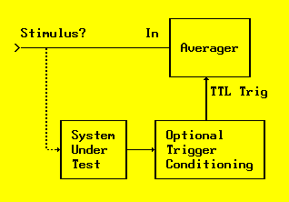
Fig. 1: Reverse Correlation Averaging
For the reverse correlation approach to be feasible, the exhibited problem must be somehow arranged to provide a trigger on each instance. Maybe there is a spurious output pulse you can use directly, such as that activation pulse from your hydraulic press controller when no operator is present. Or if your problem is with high-voltage supply arcing, maybe it can be sensed with a photodetector. Regardless of the nature of the problem, you will typically need to convert it to a TTL level transition in order to trigger the averager.
Since the reverse correlation technique looks backward in time anyway, the trigger you provide doesn't need to be especially prompt; you might employ a separate trigger conditioning circuit using fixed delays, for example, to allow isolation of a spurious pulse from a regular stream, or to trigger on a missing pulse. What this technique does require, though, is that you provide triggers only on the problem events that you are trying to correlate...not on the normal activity of the system.
Set the averager's trigger delay to a negative value, so that the trigger point would fall on the right edge of the screen, and start an average. Initially, the trace will look like the raw input: an incoherent roiling mess. But as the averager frames build up, that incoherence should settle down toward zero. Anything that seems to take a stable shape is indicative of correlation, meaning a probable stimulus since it is repeatedly preceding the trigger/problem.
No luck? Try moving the delay to still-earlier time windows, using your own judgement of the nature of your system to decide how much earlier a stimulus might arrive. If nothing shows up, it might mean that you've guessed at the wrong stimulus: Maybe it's not a mechanical vibration, but a power mains fluctuation, for example. You might decide to repeat the process using a small transformer to sample the mains voltage.
Unlike the use of averaging for noise reduction, this application is not a "magic bullet". In the first place, it only works when the trigger event follows the effective stimulus by a constant delay...it doesn't work if the stimulus merely makes the trigger event more probable, but still random in time. (It's OK, however, if the stimulus increases the probability of a trigger event that may or may not happen, but always arrives after a fixed delay when it does.)
Second, the effective stimulus must be a particular waveform, or a set of frequencies with constant phase relationships relative to the response, in order for the averager to work properly. Remember how an averager works: Any input component that isn't phase-locked to the trigger tends to average toward zero, since the peaks of one frame tend to fill in the valleys of another if they are not synchronized. If the effective stimulus you are trying to identify is merely the presence of one or more particular frequencies, of arbitrary phase, then it is no different from an uncorrelated input. In that case, this simple correlation approach is doomed...or at least, it needs some serious life support. The next column will show how spectral averaging can be used to address this problem.
To experiment with pre-trigger correlation using either waveform or spectral averaging, readers may download the author's Daqarta for Windows software. It can provide pre-trigger (or post-trigger) delays of more than 30,000 samples, using your Windows sound card as a data acquisition system.
Daqarta's built-in signal generator allows you to run many hands-on experiments without any hardware at all, since you can monitor the raw generated output directly.
All Daqarta features are free to use for 30 days or 30 sessions, after which it becomes a freeware signal generator... with full analysis capabilities. (Only the sound card inputs are ignored.)
Previous Next
Features:
Oscilloscope
Spectrum Analyzer
8-Channel
Signal Generator
(Absolutely FREE!)
Spectrogram
Pitch Tracker
Pitch-to-MIDI
DaqMusiq Generator
(Free Music... Forever!)
Engine Simulator
LCR Meter
Remote Operation
DC Measurements
True RMS Voltmeter
Sound Level Meter
Frequency Counter
Period
Event
Spectral Event
Temperature
Pressure
MHz Frequencies
Data Logger
Waveform Averager
Histogram
Post-Stimulus Time
Histogram (PSTH)
THD Meter
IMD Meter
Precision Phase Meter
Pulse Meter
Macro System
Multi-Trace Arrays
Trigger Controls
Auto-Calibration
Spectral Peak Track
Spectrum Limit Testing
Direct-to-Disk Recording
Accessibility
Data Logger
Waveform Averager
Histogram
Post-Stimulus Time
Histogram (PSTH)
THD Meter
IMD Meter
Precision Phase Meter
Pulse Meter
Macro System
Multi-Trace Arrays
Trigger Controls
Auto-Calibration
Spectral Peak Track
Spectrum Limit Testing
Direct-to-Disk Recording
Accessibility
Applications:
Frequency response
Distortion measurement
Speech and music
Microphone calibration
Loudspeaker test
Auditory phenomena
Musical instrument tuning
Animal sound
Evoked potentials
Rotating machinery
Automotive
Product test
Contact us about
your application!
Questions? Comments? Contact us!
We respond to ALL inquiries, typically within 24 hrs.INTERSTELLAR RESEARCH:
Over 35 Years of Innovative Instrumentation
© Copyright 2007 - 2023 by Interstellar Research
All rights reserved