Software for Windows
Science with your Sound Card!


Features:
Oscilloscope
Spectrum Analyzer
8-Channel
Signal Generator
Spectrogram
Pitch Tracker
Pitch-to-MIDI
DaqMusiq Generator
(Free Music... Forever!)
Engine Simulator
LCR Meter
Remote Operation
DC Measurements
True RMS Voltmeter
Sound Level Meter
Frequency Counter
Period
Event
Spectral Event
Temperature
Pressure
MHz Frequencies
Data Logger
Waveform Averager
Histogram
Post-Stimulus Time
Histogram (PSTH)
THD Meter
IMD Meter
Precision Phase Meter
Pulse Meter
Macro System
Multi-Trace Arrays
Trigger Controls
Auto-Calibration
Spectral Peak Track
Spectrum Limit Testing
Direct-to-Disk Recording
Accessibility
Data Logger
Waveform Averager
Histogram
Post-Stimulus Time
Histogram (PSTH)
THD Meter
IMD Meter
Precision Phase Meter
Pulse Meter
Macro System
Multi-Trace Arrays
Trigger Controls
Auto-Calibration
Spectral Peak Track
Spectrum Limit Testing
Direct-to-Disk Recording
Accessibility
Applications:
Frequency response
Distortion measurement
Speech and music
Microphone calibration
Loudspeaker test
Auditory phenomena
Musical instrument tuning
Animal sound
Evoked potentials
Rotating machinery
Automotive
Product test
Contact us about
your application!
Sound Card Frequency Prescaler
Introduction:
Sound cards are typically limited to frequencies in the audio range, about 20 kHz maximum. Commerical frequency counters, even the least expensive, can be used at frequencies in the tens of MHz range, and many go well beyond this.
You can increase the range of the Daqarta Frequency Counter by means of a prescaler. This is a circuit which converts the input signal into a logic-level rectangular wave and divides the frequency by an appropriate integer so the sound card sees a low-frequency square wave that the Frequency Counter can measure.
Prescalers are sometimes used ahead of commercial counters, but since there is no way for the counter to know about the division factor, it is usually set to a power of 10 so that the user can mentally move the decimal point on the counter display.
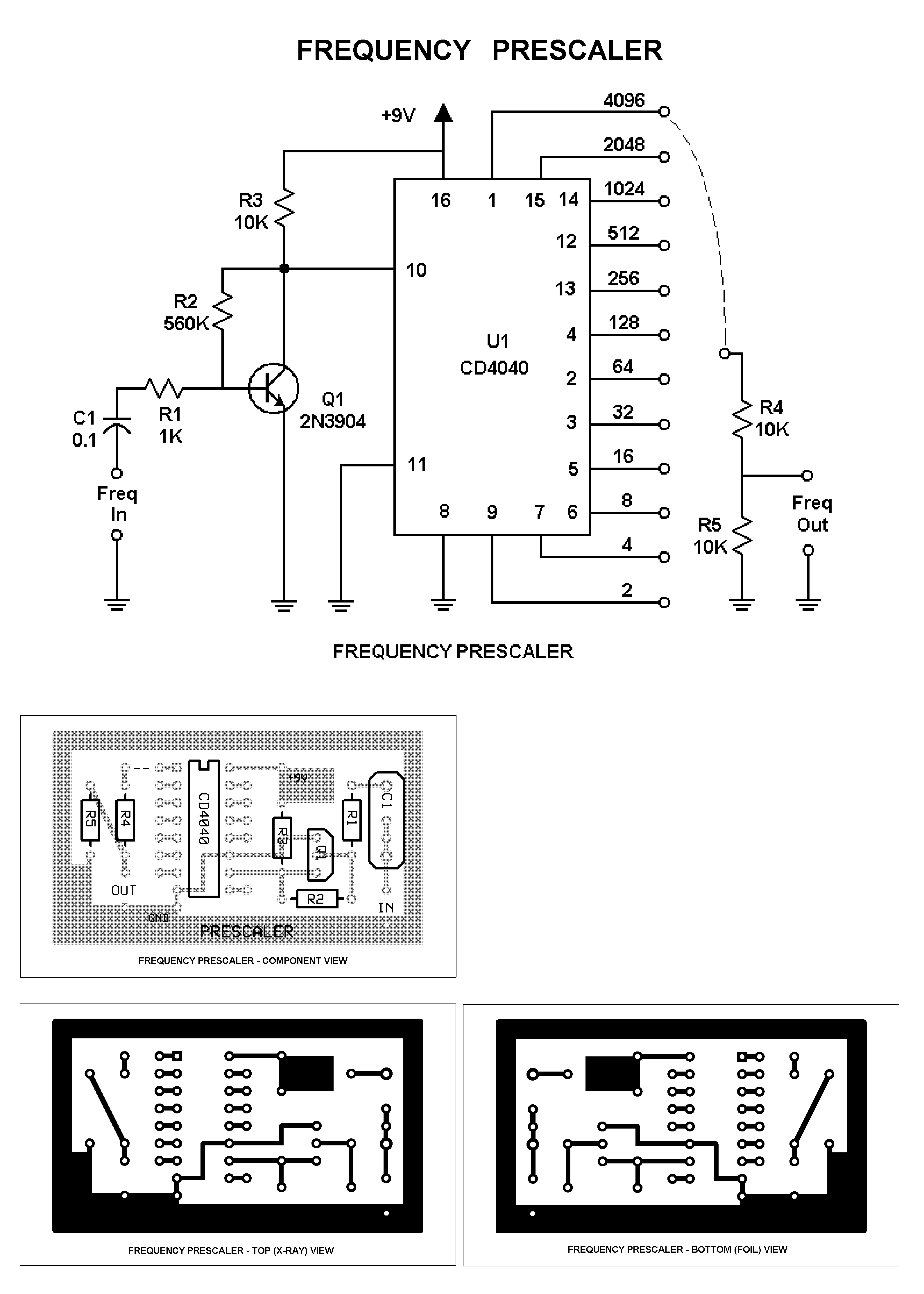
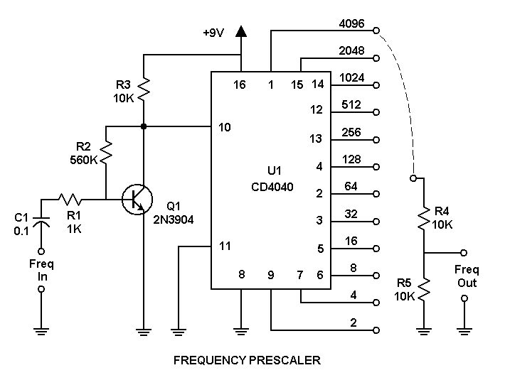
But Daqarta allows you to tell it about the prescale division factor via Fcal High, and it takes care of the conversion. There is thus no need that the factor be a power of 10, so a much simpler power-of-2 divider can be used. In the circuit above, a single CD4040 CMOS chip divides by 4096, or any lower power of 2 you select via a jumper. (The diagram shows the jumper to 4096, but 1024 is usually a better choice.)
Circuit Details:
This circuit has been designed to run from a single 9 V "transistor radio" battery. With the values shown for R2 and R3, it will accept 1 MHz input signals as small as 50 mV peak-to-peak, or 2 MHz signals as small as 100 mV.
If you reduce R2 from 560K to 56K and R3 from 10K to 1K, the battery life will be somewhat reduced, but it will accept signals as small as 500 mV at frequencies over 7 MHz.
The 2N3904 input transistor Q1 is a general-purpose high-speed switching device. The CD4040 CMOS divider chip was selected because it works well with a 9 V battery supply. If you want to use a separate 5 V supply, you can use a 74HC4040 which will work at frequencies of 15 MHz. You may need to change the R2 and R3 values, and possibly use a faster transistor for Q1, but you can use the same board layout.
The above schematic plus complete 600 DPI board and parts placement layouts suitable for printing are included in the PreScaleAll600.PNG file that is installed with Daqarta in the Documents - Daqarta - Circuits folder.
Be sure to read the Notes section of Daqarta Printed Circuits before you begin.
You can use the printed layouts directly to create your own circuit boards, with either the laser printer toner transfer method, or with the direct-draw method discussed under Printed Circuit Construction.
Alternatively, you can edit the PreScale.PCB file in the same folder to make custom modifications first. See the PCB Files discussion in Daqarta Printed Circuits for the required software to use this file, and for information on how to submit it to have boards made by a 3rd-party supplier.
Note that the component placement layout view as well as the schematic show the jumper set for a division factor of 4096 (pin 1), but a factor of 1024 (pin 14) is preferred.
Operation:
Unlike conventional counters, Daqarta maintains a constant resolution and update rate even at fairly low frequencies. If you set a division factor of 1024, then a 1.024 MHz input will give an output of 1000 Hz. This same factor will be useful at lower frequencies, even those that could otherwise be read without prescaling. For example, a 1024 Hz input will become 1 Hz. (With a factor of 4096, it would be only 0.25 Hz... still usable, but slower to update.)
However, if you anticipate mostly low frequencies you may want to switch out the prescaler. The prescaler has no trigger adjustments, whereas the Daqarta Trigger dialog allows lots of control to handle difficult signals.
When the prescaler is in use, the Fcal High Set value should be the same as the division factor, such as 1024, and the High Raw value should be 1. Fcal Low Set and Raw should both be zero.
Alternatively, if you are working at mostly high frequencies and want the Frequency Counter display to show kHz instead of Hz, you can divide the division factor by 1000 before entering it as Fcal High; if the factor is 1024, you would enter 1.024.
Note that although the display will then have the proper decimal places for kHz instead of Hz, there will be no other indication that this is so except that the Fcal button will be shown depressed.
See also Fcal Circuits, Printed Circuit Construction, Fcal Dialog, Frequency Counter
- Back to Fcal Circuits
- Ahead to Sound Card Bipolar Voltage To Frequency
- Daqarta Help Contents
- Daqarta Help Index
- Daqarta Downloads
- Daqarta Home Page
- Donate to Daqarta
Questions? Comments? Contact us!
We respond to ALL inquiries, typically within 24 hrs.INTERSTELLAR RESEARCH:
Over 45 Years of Innovative Instrumentation
© Copyright 2007 - 2026 by Interstellar Research
All rights reserved