Software for Windows
Science with your Sound Card!


Features:
Oscilloscope
Spectrum Analyzer
8-Channel
Signal Generator
Spectrogram
Pitch Tracker
Pitch-to-MIDI
DaqMusiq Generator
(Free Music... Forever!)
Engine Simulator
LCR Meter
Remote Operation
DC Measurements
True RMS Voltmeter
Sound Level Meter
Frequency Counter
Period
Event
Spectral Event
Temperature
Pressure
MHz Frequencies
Data Logger
Waveform Averager
Histogram
Post-Stimulus Time
Histogram (PSTH)
THD Meter
IMD Meter
Precision Phase Meter
Pulse Meter
Macro System
Multi-Trace Arrays
Trigger Controls
Auto-Calibration
Spectral Peak Track
Spectrum Limit Testing
Direct-to-Disk Recording
Accessibility
Data Logger
Waveform Averager
Histogram
Post-Stimulus Time
Histogram (PSTH)
THD Meter
IMD Meter
Precision Phase Meter
Pulse Meter
Macro System
Multi-Trace Arrays
Trigger Controls
Auto-Calibration
Spectral Peak Track
Spectrum Limit Testing
Direct-to-Disk Recording
Accessibility
Applications:
Frequency response
Distortion measurement
Speech and music
Microphone calibration
Loudspeaker test
Auditory phenomena
Musical instrument tuning
Animal sound
Evoked potentials
Rotating machinery
Automotive
Product test
Contact us about
your application!
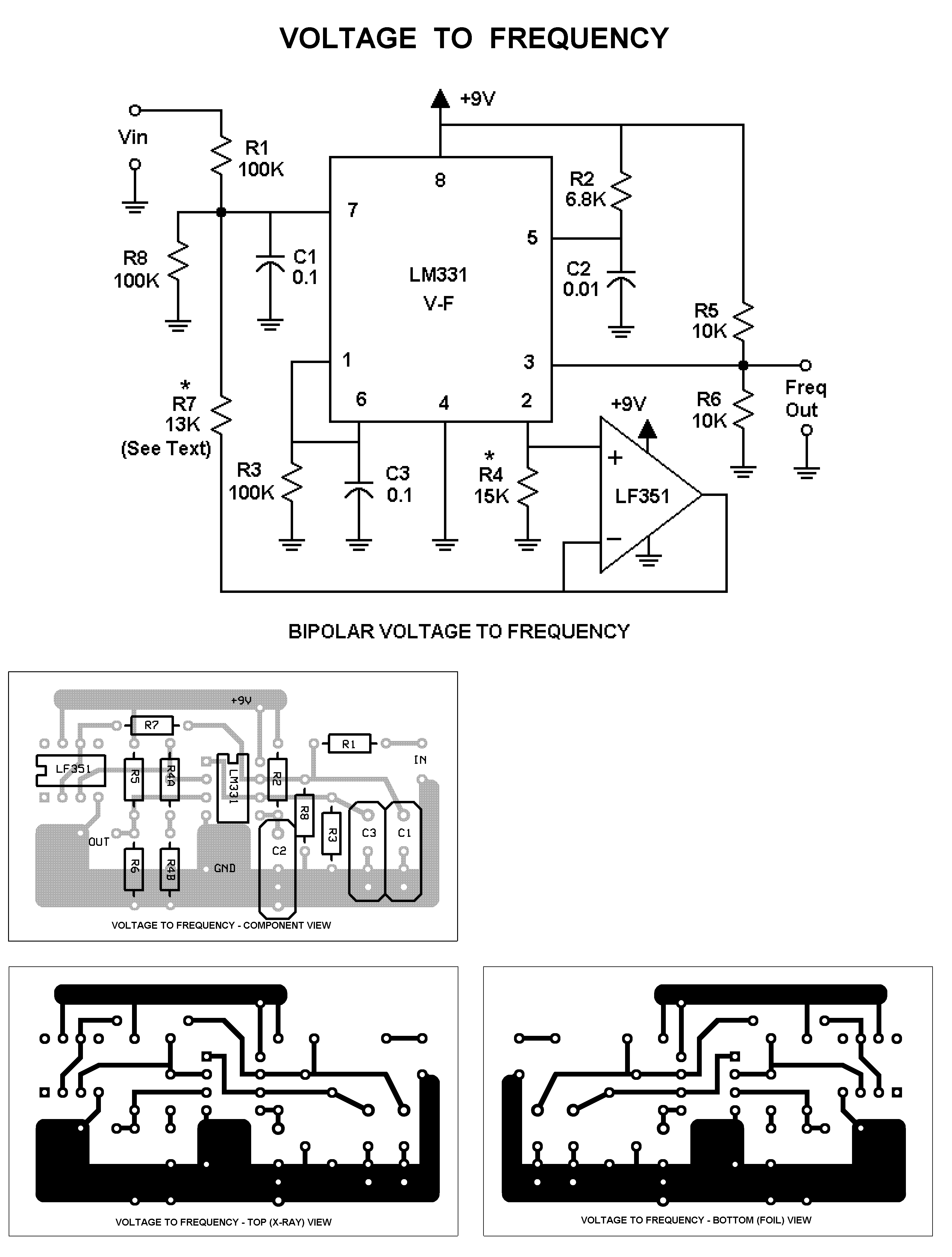
Sound Card Bipolar Voltage To Frequency
Introduction:
This circuit allows DC or very low frequency values to be read by the Daqarta Frequency Counter using the Fcal option. (See DC Measurements And Outputs for other ways to get true DC input response from your sound card.)
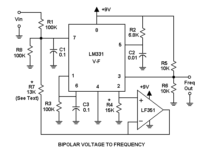
Circuit Details:
This circuit has been designed to run from a single 9 V "transistor radio" battery. With the values shown in the diagram, +/-5 V signals are translated to 1500 +/- 500 Hz, for a total range of 1000 to 2000 Hz. These are approximate values, but the circuit is very linear. Your particular components may give (say) 1555 +/-572 Hz, for a total range of 983 to 2127 Hz.
You don't need to use precision parts or trimmers, since you can calibrate this circuit using the Fcal High and Low controls to compensate. However, you may want to use high stability parts to avoid drift problems in critical applications. For general use, ordinary mylar capacitors and 1/4 watt metal film resistors will probably be adequate.
The LM331 is a very linear, temperature-compensated voltage to frequency converter, which is normally used in circuits where 0 volts gives 0 hertz. To allow bipolar operation, a constant voltage must be added to the input voltage to provide a bias. It's important that this bias voltage also be temperature compensated, but fortunately the LM331 happens to have just such a voltage available at pin 2 as part of its frequency sensitivity adjustment.
The LM331 supplies a constant, temperature-compensated 1.90 V at pin 2, across R4. The current through R4 affects the output frequency, so an LF351 op-amp buffer is used to obtain a solid copy of this voltage without drawing significant current.
That constant voltage is then summed with the input voltage via R7, R1, and R8, where its relative contribution is controlled by R7 to provide the effective bias voltage.
The LF351 is powered between the +9 V battery supply and ground, even though it is not a single-supply op-amp. That doesn't matter here because all pins are always at 1.90 V above the "negative" supply pin 4. (You can substitute a TL081 or other low bias current JFET-input amp here.)
To change the voltage range, you only need to change R4 and R7. The complete equations below are based upon the LM331 datasheet, which says that for a given voltage V7 at pin 7 the output frequency F is:
F = V7 * R4 / N
Where N = (2.09 * R3 * R2 * C2)
For R3 = 100K, R2 = 6.8K and C2 = 0.01 microfarad, we find N = 14.212.
But the R1, R7, R8 summing network affects the V7 voltage. We will assume that R1 = R8 and solve for R7, where we specify the output frequency F0 for an input of 0 V, and Fp for the full-scale positive input voltage Vp.
Note that this also assumes that F0 is big enough to allow a full-scale negative swing below it. If the positive range and negative range are to be equal, then the frequency Fn for a full-scale negative input will be:
Fn = 2 * Fp - F0
Fp and F0 must be chosen so that Fn is above zero, preferably at least 100 Hz or so. Other than that, we can ignore Fn for the rest of the calculations. Omitting a lot of tedious algebra, we find:
R7 = (Fp - F0) * 1.9 * R1 / F0 * Vp
and
R4 = N * F0 * (2 * R4 + R1) / (1.9 * R1)
For F0 = 1500, Fp = 2000, Vp = 5 V, and R1 = R8 = 100K, we get:
R7 = (2000 - 1500) * 1.9 * 100K / 1500 * 5 = 12.667K
R4 = 14.212 * 1500 * (2 * 12.667K + 100K) / 1.9 * 100K = 14.062K
To change the input voltage range from +/-5 to +/-1 while keeping the same output frequency range, we get R7 = 63.333K and R4 = 25.432K.
Note that the output is a stream of rectangular high-to-low pulses. The pulse width T is given by:
T = 1.1 * R2 * C2
For the R2 and C2 values given, this is about 75 microseconds. The maximum frequency of operation is limited to a period of about twice this, or 1 / 150 microseconds = 6.7 kHz.
The above schematic plus complete 600 DPI board and parts placement layouts suitable for printing are included in the VoltToFreqAll600.PNG file that is installed with Daqarta in the Documents - Daqarta - Circuits folder.
Be sure to read the Notes section of Daqarta Printed Circuits before you begin.
You can use the printed layouts directly to create your own circuit boards, with either the laser printer toner transfer method, or with the direct-draw method discussed under Printed Circuit Construction.
Alternatively, you can edit the VoltToFreq.PCB file in the same folder to make custom modifications first. See the PCB Files discussion in Daqarta Printed Circuits for the required software to use this file, and for information on how to submit it to have boards made by a 3rd-party supplier.
Note that in the component placement layout the total R4 value is shown as series resistors R4A and R4B. This allows you to combine values to get closer to the computed value for R4, in case you want to use this same circuit in some other context. (In that case, you may want to edit the PCB file to allow R7 to be made up of 2 series values as well.)
In Daqarta, however, the Fcal High and Low controls make these series values completely superfluous; you can use any single value that is reasonably close. If you bend the R4 resistor so that the leads are 0.5 inch apart instead of the standard 0.4 inch, you can insert it just below the R4A position and it will reach ground without needing a separate jumper.
Calibration:
To calibrate the Voltage-to-Frequency converter, apply a known voltage to the input. Set Fcal High Set to the known value and conclude the entry with CTRL+Enter to simultaneously set Fcal High Raw to the current frequency.
Then replace the known input with a direct connection to ground (0 volts). Set Fcal Low Set to 0 and conclude the entry with CTRL+Enter to set Fcal Low Raw to the current frequency.
See also Fcal Circuits, Printed Circuit Construction, Fcal Dialog, Frequency Counter
- Back to Sound Card Frequency Prescaler
- Ahead to Sound Card Temperature To Frequency
- Daqarta Help Contents
- Daqarta Help Index
- Daqarta Downloads
- Daqarta Home Page
- Donate to Daqarta
Questions? Comments? Contact us!
We respond to ALL inquiries, typically within 24 hrs.INTERSTELLAR RESEARCH:
Over 45 Years of Innovative Instrumentation
© Copyright 2007 - 2026 by Interstellar Research
All rights reserved