Software for Windows
Science with your Sound Card!


Features:
Oscilloscope
Spectrum Analyzer
8-Channel
Signal Generator
Spectrogram
Pitch Tracker
Pitch-to-MIDI
DaqMusiq Generator
(Free Music... Forever!)
Engine Simulator
LCR Meter
Remote Operation
DC Measurements
True RMS Voltmeter
Sound Level Meter
Frequency Counter
Period
Event
Spectral Event
Temperature
Pressure
MHz Frequencies
Data Logger
Waveform Averager
Histogram
Post-Stimulus Time
Histogram (PSTH)
THD Meter
IMD Meter
Precision Phase Meter
Pulse Meter
Macro System
Multi-Trace Arrays
Trigger Controls
Auto-Calibration
Spectral Peak Track
Spectrum Limit Testing
Direct-to-Disk Recording
Accessibility
Data Logger
Waveform Averager
Histogram
Post-Stimulus Time
Histogram (PSTH)
THD Meter
IMD Meter
Precision Phase Meter
Pulse Meter
Macro System
Multi-Trace Arrays
Trigger Controls
Auto-Calibration
Spectral Peak Track
Spectrum Limit Testing
Direct-to-Disk Recording
Accessibility
Applications:
Frequency response
Distortion measurement
Speech and music
Microphone calibration
Loudspeaker test
Auditory phenomena
Musical instrument tuning
Animal sound
Evoked potentials
Rotating machinery
Automotive
Product test
Contact us about
your application!
AC-to-DC Input Level Shifter and Limiter
The circuit below allows sound card outputs or other low-voltage AC sources to drive high-impedance 0 to +5 VDC inputs such as those on Arduino or Numato devices.
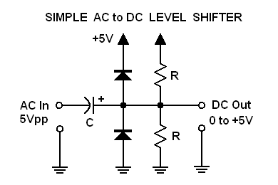
Ideally the input signal should be less than 5 volts peak-to-peak, which typically includes all sound cards. If it is somewhat more the diodes will limit the output to the 0-5 VDC range to protect the Arduino or Numato inputs.
The capacitor C and resistors R form a high-pass filter that limits the response at low frequencies. To compute the lower limit, the resistors should be considered to be in parallel, hence half the nominal R value. The resulting formula for the -3 dB frequency then becomes:
F = 1 / (pi * R * C)
When the AC input voltage is 0, the output baseline will be determined by the resistors acting as a voltage divider on the +5 VDC supply. With both resistors the same value, that will be at +2.5 VDC. The R values should typically be in the range of 10K to 1 Megohm, but are not critical as long as they are nominally the same. Note, however, that these resistors (in parallel) act as a load to any external source that drives this circuit. High values are thus better for not loading down the source, but are more likely to pick up noise from power lines, appliances, fluorescent lights, etc.
For example, with both R values at 10K and C at 1 microfarad the response will be -3 dB down at about 32 Hz. Raising the R values to 100K will lower the cutoff to 3.2 Hz. Raising further to 1 Megohm will give 0.32 Hz, though as noted above will make the input more sensitive to noise.
Of course you can always raise the capacitor value to get a low cutoff frequency with low R values, if your driving source can handle the load.
The C polarity is shown under the assumption that you will be using an electrolytic type, but for applications that don't need to deal with very low frequencies you can use an ordinary film or ceramic type with a much smaller value.
This circuit is especially useful with the DaquinOscope or the DC Chart Recorder macro mini-apps, where you want to view an AC waveform on one or more channels. The waveform will be shifted up to swing about 2.5 VDC instead of the original AC ground, but will have the same relative voltages. The shape may change if the input is not a sine wave, due to the high-pass filter action.
Another use of this circuit is with the Arduino_Counter to measure frequencies or to count events. This uses the Arduino's digital inputs instead of analog. If the input source is a rectangular wave or pulse, you can use a fairly small C (high cutoff frequency) because you really only need the edge transitions to pass. Note that with very slow sine wave inputs, the transitions through the digital threshold voltage range can be so slow that circuit noise can register as spurious edges.
- Back to Sound Card Input Range and Limiter Circuits
- Ahead to RIAA Phono Equalization Testing
- Daqarta Help Contents
- Daqarta Help Index
- Daqarta Downloads
- Daqarta Home Page
- Donate to Daqarta
Questions? Comments? Contact us!
We respond to ALL inquiries, typically within 24 hrs.INTERSTELLAR RESEARCH:
Over 45 Years of Innovative Instrumentation
© Copyright 2007 - 2026 by Interstellar Research
All rights reserved