Software for Windows
Science with your Sound Card!


Features:
Oscilloscope
Spectrum Analyzer
8-Channel
Signal Generator
Spectrogram
Pitch Tracker
Pitch-to-MIDI
DaqMusiq Generator
(Free Music... Forever!)
Engine Simulator
LCR Meter
Remote Operation
DC Measurements
True RMS Voltmeter
Sound Level Meter
Frequency Counter
Period
Event
Spectral Event
Temperature
Pressure
MHz Frequencies
Data Logger
Waveform Averager
Histogram
Post-Stimulus Time
Histogram (PSTH)
THD Meter
IMD Meter
Precision Phase Meter
Pulse Meter
Macro System
Multi-Trace Arrays
Trigger Controls
Auto-Calibration
Spectral Peak Track
Spectrum Limit Testing
Direct-to-Disk Recording
Accessibility
Data Logger
Waveform Averager
Histogram
Post-Stimulus Time
Histogram (PSTH)
THD Meter
IMD Meter
Precision Phase Meter
Pulse Meter
Macro System
Multi-Trace Arrays
Trigger Controls
Auto-Calibration
Spectral Peak Track
Spectrum Limit Testing
Direct-to-Disk Recording
Accessibility
Applications:
Frequency response
Distortion measurement
Speech and music
Microphone calibration
Loudspeaker test
Auditory phenomena
Musical instrument tuning
Animal sound
Evoked potentials
Rotating machinery
Automotive
Product test
Contact us about
your application!
DaqPort Arduino Sketch
- Introduction
- Supported Arduino Boards
- Installing DaqPort
- Command Summary
- 0x8n Read Unsigned Integer Word
- 0x9n Read Unsigned Long Dword or Time Stamp
- 0xAn Read Analog Input Pins
- 0xBn Bit (Digital Pin) Read, with Time Stamp
- 0xCn PWM (Pulse Width Modulation) Control
- 0xDn Digital Output / Mode Set (Single Pin)
- 0xEn EEPROM Commands
- 0xF0 Extended Functions
- 0x0D Read DaqPort Version
- 'A' Set ADC Clock Prescaler
- 'B' Set New Baud Rate
- 'b' Set ADC Bits and Voltage Range
- 'C' Read Arduino Chip Signature
- 'D' Set Trigger Delay
- 'F' Set Oscillator Frequency And Phase
- 'h' Set Trigger Hysteresis
- 'I' Set Interrupt Rate
- 'O', 'o' Get Wavetable Oscillator Data
- 's' Set Sample Delay
- 'T' Set Trigger Parameters
- 't' Set Time Stamp
- 'W' Set Wait Timeout
- 0xF1 Burst Acquisition (Scope) Function
- 0xF2 Read 1024 10-bit Analog Samples
- 0xF3 Read 1024 8-bit Analog or Digital Samples
- 0xFC Multi-Pin RCtime Measurements
- 0xFD Multi-Pin Digital Write and pinMode
- 0xFE Event / Race Timer
Introduction:
DaqPort.ino is an Arduino "sketch", which is the Arduino-speak term for code that resides in the Arduino's program memory. DaqPort allows the Arduino to act as a peripheral device, controlled by Daqarta via USB / serial port commands.
This arrangement lets the Arduino do things it is best at, such as DC-coupled data acquisition, while Daqarta handles processing and display.
In particular, DaqPort enables the Arduino to be used with several macro mini-apps that are included with Daqarta:
DaquinOscope multi-channel oscilloscope
DC_Chart_Recorder: Up to 8 analog or digital channels
Arduino_Race_Timer: Up to 6 entrants or events
Arduino_Counter: Period, frequency, pulse width, event counter
Arduino_Oscillators: 4 square waves with frequency and phase
Arduino_RCtime multi-pin resistance/capacitance meter
Ardino_Meter simple voltmeter
It also supports basic functions such as reading analog inputs, reading and writing digital ports, reading the current time stamp, setting modes, and pulse width modulation. These may become the basis for future mini-apps, or you can create your own custom macro applications.
Note that DaqPort does not require Daqarta; it can be used by any software that follows the DaqPort serial protocol, and can be modified or extended as desired.
Although DaqPort uses serial communications, it does not use the usual terminal-type serial protocol to send verbose strings back and forth. Instead, it uses mostly binary values. A terminal approach might send a command string like "adc read 0" (10 bytes, plus a carriage return) to read the voltage on ADC 0, whereas DaqPort does this in a single 0xA0 hex byte (hA0 in Daqarta's macro notation).
A terminal system then typically echoes back the original text command and appends a response like "1023", making the total response string 16 bytes. This requires parsing and conversion to a binary value for further use. Daqarta simply reads a 2-byte binary value.
For many of the DaqPort commands, a single byte specifies the type of command in the high nybble, and the specific channel, pin, or data requested in the low nybble. For example, in the 0xA0 command mentioned above the A indicates 'Analog read' while the 0 indicates 'analog input A0'. You would use 0xA1 to 0xA5 to read the other analog inputs. DaqPort responds by sending a 10-bit analog value as two bytes. (0xAF is a special 'read all' option with a different read protocol, discussed later.)
Other commands use the first byte similarly, plus additional bytes (or 2-byte or 4-byte integers) as needed. For example, 0xD0 to 0xDF are digital output or mode set commands, with the low nybble 0-F specifying digital pin 0-15. This command always reads a second byte; if that byte's high nybble is 0x40 then it is a mode set command, with the low nybble of that second byte indicating the mode to be set for the given pin. (0=INPUT, 1=OUTPUT, 2=INPUT_PULLUP.) Otherwise, the command is a digital write that sets or clears the specified pin according to the state of the low bit in the second byte.
Commands 0xF0 and above are extended functions. 0xF0 itself is for miscellaneous functions, with a second byte specifying the function. For example, if the second byte is 0x0D the command returns the DaqPort version in a format that allows the _ComDev_Scan macro subroutine to identify the device as an Arduino running DaqPort.
NOTE that two-byte commands may be given by sending an integer word. In this case the low byte of the integer is the one that is sent first. The integer for the above command would thus be 0x0DF0, or h0DF0 in Daqarta macros. _ComDev_Scan thus uses Port#D2=h0DF0, but you could alternatively use a string format such as Port=$w(h0DF0). To code the bytes separately, you could use Port=$(hF0) + $(h0D) or even Port#D1=hF0 followed by Port#D1=h0D. See the USB / Serial Communications Port Access topic for details.
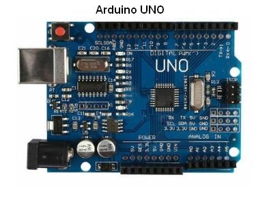
Supported Arduino Boards:
Arduino boards are "open hardware" designs that are manufactured by various suppliers. There are many different Arduino models, mostly pioneered by Adafruit. Other vendors usually refer to their models by the same names as the corresponding Adafruit model, or say "compatible with".
DaqPort was designed and tested on UNO models, specifically the UNO R3 from Adafruit (no longer available from them), and also some cheap imports. All performed essentially the same. Note that some of the cheaper imports use the CH340 USB-to-Serial chip, which may require that you download and install a driver for it. This is pretty straightforward, and there are plenty of Web tutorials to guide you.
DaqPort was also tested on the Arduino Metro 328 from Adafruit via Amazon. (You might choose to buy from Amazon, instead of directly from Adafruit, to take advantage of Amazon shipping.) The Metro 328 is essentially identical to the UNO, but unlike most UNO offerings it doesn't come with a USB cable. That's an issue here because it uses a "micro" USB connector on the board instead of the common "doghouse" style found on many standard USB cables. (See Cables and Connectors.)
Other Arduino models may be compatible. The things to look for are the CPU type (ATmega328P), the clock speed (16 MHz), and the operating voltage (5 V). There are 3.3 V models which may be suitable for most basic DaqPort functions, but some mini-apps like Arduino_RCtime and DaquinOscope may need revisions.
Please note that there is a model called the Metro M0 Express which uses an entirely different CPU running at a different clock speed. Not tested, and not recommended.
Installing DaqPort:
Before you can install DaqPort, you must first install the Arduino software package (desktop IDE). Go to <https://www.arduino.cc/en/guide/HomePage>. Skip over the "Code online on the Arduino Web Editor" section and go to "Install the Arduino Desktop IDE". Click on "Windows", then follow the download page link and click on "Windows installer, for Windows XP and up" under "Download the Arduino IDE". Important: Don't get the Zip package, since it requires manual installation of drivers.
It would be a Good Thing to make a donation when prompted, but it's not mandatory.
The installer download (arduino-1.8.10-windows.exe) is about 117 MB. When the download is complete, navigate to its location (typically in your Downloads folder) and run it. When prompted, accept all the defaults. The installer progress bar may move along and then appear to hang for a few minutes near the end, but be patient. When it's done, click Finish to close the installer.
After the installer closes, go back to the home page above and click on "UNO". Scroll down to "Use your Arduino Uno on the Arduino Desktop IDE" and connect your Arduino to a USB port as shown. Wait a moment for Windows to recognize it and automatically install the needed driver(s). (You can skip the section titled "Install the board drivers".)
When you get to "Open your first sketch", you first need to open the Arduino IDE by double-clicking its desktop icon, then return to your browser and follow the instructions to load the LED Blink demo, set or verify the board type as "Arduino/Genuino Uno", and set the COM port. Typically the Port option will only show one port other than "Serial ports", but you still have to click on it to select it.
The toolbar at the top of the IDE shows a checkmark icon which you can click to verify the Blink sketch before you upload it to the board, or you can just click the right-arrow button to check and then upload. The red LED on the board should start blinking at one second on, one second off.
Now you are ready to upload DaqPort. In the Arduino IDE, click on the File menu and select Open. The "Open Arduino sketch" dialog will open in the default Arduino folder; you'll need to navigate up to Documents, then down to Daqarta - Utility and click on DaqPort.ino. The DaqPort sketch will open in the IDE.
Now verify and upload the sketch as you did for Blink. At the bottom of the IDE screen you'll see a black region with a report of memory usage, including a warning in red: "Low memory available, stability problems may occur." This is normal, and is due to the fact that DaqPort uses a lot of the limited 2048-byte RAM variable memory to store arrays for 1024 samples of DaquinOscope input data and/or wavetable oscillator data. (The size of the DaqPort program code is not a factor in this warning, since only half of the 32K flash program space is used.)
The "stability" warning is presumably due to the fact that the processor stack also uses space in the RAM, and the stack-intensive operations used in some C programs could cause a growing stack to collide with the variable area. DaqPort uses the stack sparingly, however, and this issue is not encountered.
Command Summary:
0x8n  Read unsigned integer word intAr[n], where n = 0-7

0x9n  Read unsigned long dword longAr[n], where n = 0-7
                If n = 15 (0x9F), read msec time stamp
                If n = 14 (0x9E), read usec time stamp
                If n = 13 (0x9D), read last 0xBn time stamp

0xAn  Read analog input pin An, if n = 0-5
                If n = 0x0F, read A0-A5

0xBn  Bit (pin) {\b\i n} read, where n = 0-15
                If n = 0, read PIND (pins 0-7) as single byte
                If n = 1, read PINB (pins 8-15) as single byte
                If n = 15, return integer with PIND low byte, PINB high
                In all cases, time stamp is saved for subsequent 0x9D read

0xCn  PWM output control on pin n = 3, 5, 6, 9, 10, or 11
                Second byte is On time 0-255

0xDn  Digital output or mode set on pin n
                Second byte high nybble 0x40 is mode set, low nybble = mode 0-2
                Else second byte LSB is new state

0xEn  EEPROM commands.  n = 0x0F returns EEPROM size integer
                If n has 0x08 set it is an EEPROM write command:
                    Low bits of n = 1, 2, or 4 to set write size
                    Next 2 bytes are integer write destination
                    Following are 1,2,4 bytes of data to write
                Else it is an EEPROM read command:
                    Low bits of n = 1, 2, or 4 read size
                    Next 2 bytes are integer read start
                    Returns 1, 2, or 4 bytes of data

0xF0   Miscellaneous extended functions, second byte is function code:
            0x0D =  Read DaqPort version
            'A' = Set {\b A}DC clock prescaler
            'B' = Set new {\b B}aud rate
            'b' = Set ADC {\b b}its 8/10, also 1.1 or 5.0V
            'C' = Read {\b C}hip signature (3 bytes)
            'D' = Set trigger {\b D}elay
            'F' = Set oscillator {\b F}requency and phase
            'h' = Set trigger {\b h}ysteresis
            'I' = Set {\b I}nterrupt rate
            'O' = Get 1K waveform {\b O}scillator cycle data
            'o' = Get 256-byte waveform {\b o}scillator cycle data
            's' = Set {\b s}ample delay for fast non-interrupt sampling
            'T' = Set {\b T}rigger parameters
            't' = Set Time Stamp for 0xBn Digital Bit Read
            'W' = Set loop {\b W}ait timeout

0xF1   Burst Acquisition (scope) command
            Second byte is analog pin bitmap
            Digital acq if 0x80, low 2 bits = digital port mode

0xF2   Read 1024 samples of 10-bit burst data after 0xF1 return

0xF3   Read 1024 bytes of 8-bit burst data after 0xF1 return

0xFC   RCtime measures discharge time constant on up to 6 pins
            Second byte is bitmap, PORTD pins 2-7 only.
                Bit 0 = 1 to return counts, else usec
                Bit 1 = 1 to use Rsens high mode, else Rsens grounded
            Following word is discharge delay, pos = usec, neg = msec

0xFD   Multi-pin Digital write.
            Second byte high nybble = direct, pullup, DDRD, masked, set mask
                Low nybble 1 = PORTD, 2 = PORTB, 3 = Both
            Third byte is data for PORTD or PORTB if above = 1 or 2
            Forth byte is data for PORTB, only if Both

0xFE   Event/Race Timer
            Second byte = Trigger pin, polarity
            Third byte = Signal pin, polarity, options
            Fourth byte = Event pinmap, polarity
Read Unsigned Integer Word:
    Command Byte: 0x8n, n = 0-7
    Returns: 2-byte intAr[0]-[7]
DaqPort provides 8 integer word values that are used internally as working values, and may also be used as return values from some functions. In the source code they are called intAr[0] through intAr[7], and may be read via serial commands 0x80 through 0x87 (h80 through h87 in Daqarta macros).
For example, the Analog Read All command 0xAF returns the values of the six analog input pins A0-A5 in 0x80 though 0x85. Similarly, the 0xF1 Burst Acquisition (scope) command returns the number of timeout hits in 0x87, as do the 0xFC RCtime and the 0xFE Event/Race Timer commands.
To read a value into a Daqarta variable, you send the read command to the port, then read the value:
Port#D1=h82    ;Send 1-byte command to read 0x82
UA=Port?2      ;Read 2-byte word from port into variable UA
Since these are unsigned words, values may range from 0 to 65535.
Read Unsigned Long Dword:
    Command Byte: 0x9n, n = 0-7, 13, 14, 15
    Returns: 4-byte longAr[0]-[7] or time stamp
Similar to the above Read Integer Word, DaqPort provides 8 unsigned long dword values that are used internally as working values, and may also be used as return values from some functions. In the source code they are called longAr[0] through longAr[7], and may be read via serial commands 0x90 through 0x97 (h90 through h97 in Daqarta macros).
Internally, longAr[0] through longAr[3] are the phase steps for oscillators 0-3, and longAr[4] through longAr[7] are the corresponding phase accumulators.
The same values are used to return 0xFC RCtime counts or microseconds for corresponding pins. They are also used for elapsed time on 0xFE Event/Race pins.
In addition to reading the above longAr[] values, this function can also read time stamp values:
0x9F   Read millisecond time stamp
0x9E   Read microsecond time stamp
0x9D   Read last 0xBn digital read time stamp
The time stamps are the elapsed time since the Arduino was started, in milliseconds or microseconds. These are 32-bit counters internal to the Arduino, which wrap around to 0 on overflow. 2^32 milliseconds is about 49.71 days, while 2^32 microseconds is about 71.58 hours. Note that the resolution of the microsecond counter is 4 microseconds, so values are always multiples of 4.
To read a long value into a Daqarta variable, you send the read command to the port, then read the value:
Port#D1=h92    ;Send 1-byte command to read 0x92
UA=Port?4      ;Read 4-byte dword from port into variable UA
Note: Since these are unsigned dwords, values may range from 0 to 2^32-1. However, Daqarta integers such as the above UA example are signed, so they extend from -2^31 to +2^31-1. To prevent problems with later handling of returned values of 2^31 and above, you can convert unsigned integers to floating-point via A=uns(UA.
Read Analog Input Pins:
    Read Single Input:
    Command Byte: 0xAn, n = 0-5
    Returns: 2-byte integer 0-1023

    Read All Inputs:
    Command Byte: 0xAF
    Returns: 2-byte integer for A0, rest via 0x81-5
The Arduino Uno has 6 analog input pins designated A0 to A5. You can read individual inputs via commands 0xA0 to 0xA5 (hA0 through hA5 in Daqarta macros).
These return 10-bit values, so require 2-byte reads. To read the value into a Daqarta variable, you first send the read command to the port, then read the value:
Port#D1=hA3    ;Send 1-byte command to read analog input A3
UA=Port?2      ;Read 2-byte word from port into variable UA
You can read all 6 inputs via the single command 0xAF (hAF). The analog values are read into intAr[0] through intAr[5], where they can be read via 0x80 through 0x85 commands. You don't actually need the 0x80 command, since the 0xAF command returns the A0 value directly. A typical Read All sequence would be:
Port#D1=hAF    ;Send 1-byte command to read all analog inputs
U0=Port?2      ;Read A0 value from port into variable U0
Port#D1=h81    ;Request intAr[1] holding A1 value
U1=Port?2      ;Read it into variable U1
Port#D1=h82    ;Request intAr[2] holding A2 value
U2=Port?2      ;Read it into variable U2
Port#D1=h83    ;...
U3=Port?2
Port#D1=h84
U4=Port?2
Port#D1=h85
U5=Port?2
As you can see, the above doesn't use any less code than 6 separate reads, but it does have the advantage that the actual ADC reads are all done on the initial command. The values are thus much closer to "simultaneous" because there are no serial port delays between them, which might become more of an issue if you use slow baud rates. (Daqarta defaults to 115200 baud, which is the fastest rate that was found to be reliable on the Arduino.)
Please note that the ADC conversion speed is controlled by the ADC Clock Prescaler, discussed below. The Arduino defaults to the slowest clock speed (125 kHz) on power-up. If you change the speed, either explicitly or by running the DaquinOscope macro mini-app (which defaults to 2 MHz), subsequent 0xAn reads will be affected.
Bit (Digital Pin) Read:
    Read Single Pin:
    Command Byte: 0xBn, n = pin number
    Returns: 1-byte state (0,1)
             Also sets time stamp for 0x9D read

    Read PIND:
    Command Byte: 0xB0
    Returns: 1-byte bitmap

    Read PINB:
    Command Byte: 0xB1
    Returns: 1-byte bitmap

    Read All Pins:
    Command Byte: 0xBF
    Returns: Byte 0 = PIND
             Byte 1 = PINB
The Arduino Uno has two 8-bit digital ports, PIND (bits 0-7) and PINB (bits 8-15). Bits 0 and 1 are used for the serial port, and bits 14 and 15 are not connected to the header. Bits 2-13 correspond to their respective pin numbers.
You can read the state of any individual pin 2-13 using an 0xBn command, where n is the pin number. The state will be returned as a single byte with a value of 0 or 1:
Port#D1=hB2    ;Send 1-byte command to read digital bit 2.
UA=Port?1      ;Read 1 byte from port into variable UA
0xB0 reads PIND bits 0-7 and returns a single byte, while 0xB1 similarly reads PINB bits 8-15:
Port#D1=hB0    ;Send 1-byte command to read PORTB
UD=Port?1      ;Read 1 byte from port into variable UD
Port#D1=hB1    ;Send 1-byte command to read PORTB
UB=Port?1      ;Read 1 byte from port into variable UB
0xBF reads both PIND and PINB and returns an integer word with bits 0-15 set accordingly.
Port#D1=hBF    ;Send 1-byte command to read all digital bits
UF=Port?2      ;Read 2-byte word from port into variable UF
If it is important to know when a pin state is read, you can use Daqarta's High Resolution Timer or UTC Time functions just before or after the pin read. Alternatively, you can use DaqPort's built-in time stamp functions. The 0x9F function reads milliseconds since the Arduino started, while 0x9E reads microseconds. Like the Daqarta functions, these are separate time stamps you read just before or after the pin read. Instead, you can use 0x9D to read a time stamp that is recorded at the time of the most-recent pin read. (You must first set that to record milliseconds or microseconds via the 0xF0,'t' Extended Function discussed below.)
PWM (Pulse Width Modulation) Control:
    Command Byte 0: 0xCn, n = pin
    Command Byte 1: On value, 0-255
    Returns: None
The Arduino Uno supports pulse width modulation (PWM) on digital pins 3, 5, 6, 9, 10, and 11. These pins can produce rectangular waves that are high (On) for an adjustable proportion of their cycle, and low (Off) for the rest.
The 0xCn command sets the pin number in n, and must be followed by a second byte to specify the On value. For example, to set pin number UP with an On value UV you could use:
Port#D2=UV<<8 + hC0 + UP
This shifts the UV value up by 8 bits so it will occupy the second byte sent, as long as UV is 255 or less. Similarly, UP must be less than 15 so that it won't overflow the low nybble when added to hC0 to form the low byte (sent first).
Or you could do the same thing with the command in string format to show the byte positions more clearly:
Port=$(hC0 + UP) + $(UN)
Pins 5 and 6 have PWM frequencies of about 980 Hz, while the rest are about 490 Hz.
You can use the PWM rectangular wave directly (with a series resistor) to control the brightness of an LED. Or you can use it to drive a switching transistor to provide more power, to control a heating element or the speed of most motor types.
Alternatively, you can try a simple low-pass RC filter to smooth the rectangular wave into something closer to pure DC.
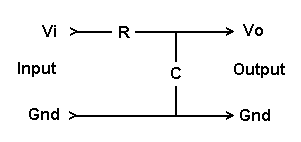
F = 1 / (2 * pi * R * C).
Note that you'll need to set a very low cutoff frequency F (large R and C) to get decent smoothing, but a large R means a high output impedance so any resistance connected to the output must be much higher still.
Digital Output / Mode Set (Single Pin):
    Output To Pin n:
    Command Byte 0: 0xDn
    Command Byte 1: Output state (low bit)
    Returns: None

    Pin n Mode Set:
    Command Byte 0: 0xDn
    Command Byte 1: 0x40 + 0, 1, or 2
    Returns: None
The 0xDn command allows you to set the state of any digital output pin, or to set its operating mode. The pin number is given by n in the low nybble of the command byte, from 0-15 (although normally only pins 2-13 should be used).
The output to be set is specified via a second byte, where the lowest bit is the target state. (The other bits are ignored.) If the pin number is in Daqarta variable UP and the target state is in US, this command will set the state:
Port#D2=US<<8 + hD0 + UP
The following is equivalent:
Port=$(hD0 + UP) + $(US)
However, before you attempt to use a pin you should first set its operating mode. This is done by setting the high nybble of the second byte to 0x40. The desired mode is then given by the low two bits:
0 = INPUT
1 = OUTPUT
2 = INPUT_PULLUP
This macro code will set the mode to OUTPUT:
Port=$(hD0 + UP) + $(h41)
The INPUT_PULLUP mode means that the pin is configured as an input, but with an internal resistor connected to the positive supply voltage (5 volts in the case of the Arduino Uno). The value of the resistor is specified by the manufacturer to be between 20K and 50K, and is typically close to 35K.
Without a pullup (or pull-up) in the plain INPUT mode, the input impedance is very high. This makes the input good for (say) sensing a finger touch, or for RCtime measurements, but also means it is sensitive to noise and stray electrical fields causing spurious state changes.
A typical use of the INPUT_PULLUP mode would be to sense the state of an external switch. The switch would be wired between the input and ground, so when the switch is closed it forces the input state to 0 (ground or LOW) so it is not susceptible to noise. When the switch is open the pullup "pulls up" the input to 1 (5 V or HIGH), where due to the low impedance of the pullup it is also highly resistant to noise. Notice that there is no point in time during switch operation where the input is left floating at a high-impedance condition, so its logical state is always reliably 0 or 1.
Note that if the mode of the pin has been set to INPUT, then attempting to set its state high (as if it was an output) will actually enable the internal pullup resistor, the same as setting the mode to INPUT_PULLUP above. Setting INPUT mode always disables the pullup.
EEPROM Commands:
    Get EEPROM Size:
    Command Byte: 0xEF
    Returns: 2-byte integer

    Write n Bytes To EEPROM:
    Command Byte 0: 0xE8 + n, n = 1, 2, 4
    Command Bytes 1,2: Address, integer word
    Data: 1, 2, or 4 bytes to write
    Returns: None

    Read n Bytes From EEPROM:
    Command Byte 0: 0xE0 + n, n = 1, 2, 4
    Command Bytes 1,2:  Address, integer word
    Returns: 1, 2, or 4 bytes
The Arduino Uno contains an EEPROM (Electrically Eraseable Programmable Read-Only Memory) that holds 1024 bytes. Unlike normal DaqPort variables, this is non-volatile memory that is retained even without power. DaqPort doesn't use this memory for anything by default; it's completely free for your use.
For example, if you have more than one Arduino and they are wired to different external hardware or systems, you might want a way for your custom macros to tell them apart. Then, even if they get plugged into different USB ports, you can insure that the correct test runs on the proper device. You can do this by storing a unique ID code in each Arduino's EEPROM.
The 0xEF command returns an integer word holding the size of the EEPROM, which is 1024 for the Uno:
Port#D1=hEF        ;Request EEPROM size
QS=Port?2          ;QS = size
You can write 1, 2, or 4 bytes to the EEPROM with a single command. Add 8 to the number of bytes and use it as the low nybble n of the 0xEn command, followed by the 2-byte start address (0-1023) within the EEPROM, then the data bytes in the order you want them to appear. For example, if you want to write 4 data bytes from dword variable UD to address UA the macro code would look like:
Port=$(hE8 + 4) + $w(UA) + $d(UD)
Note that the above sends the low byte of UD first, but if you want to send in high-to-low order use $4(UD) instead of $d(UD). See Simple Data Write Commands under USB / Serial Communications Port Access.
Similarly, you can read 1, 2, or 4 bytes from the EEPROM by not adding 8 to the number of bytes before using it as the low nybble n of the 0xEn command, followed by the 2-byte start address (0-1023) within the EEPROM. For example, to read 1 byte from address UA into variable UD you could use:
Port=$(hE1) + $w(UA)       ;Read one byte from UA
UD=Port?1                  ;Into UD
Extended Functions 0xF0:
The DaqPort functions that start with an 0xFn byte are more specialized than those previously discussed. Those starting with 0xF0 are miscellaneous functions, many of which support the 0xF1 Burst Acquisition function used by by the DaquinOscope macro mini-app.
Read DaqPort Version:
    Command Byte 0: 0xF0
    Command Byte 1: 0x0D
    Returns: 0xF0, 0x76, VERS_LO, VERS_HI
This function is provided for use by the _ComDev_Scan macro subroutine that allows a macro to automatically find the COM port that an Arduino is plugged into, without having to first manually open Windows Control Panel and look under the Ports group in the Device Manager.
The command is 0x0DF0, which is sent as an 0xF0 byte followed by an 0x0D byte. The latter is an ordinary ASCII carriage return byte that is expected by most terminal-type serial devices to end a command string. When such a device (including the Numato family supported by the DC Chart Recorder) reads this, it assumes that the command itself was simply the non-ASCII 0xF0 and responds immediately without looking for further bytes.
The reponse is typically just an echo back of the command, possibly with some error string included. It is unlikely that any non-DaqPort device will give the proper response by coincidence, which is 0xF0 followed by ASCII 'v', then the DaqPort minor and major version bytes.
If you just want to read the version, you can easily isolate the last two bytes (high word) from the 4-byte return string:
Port#D2=h0DF0      ;Send 0xF0, followed by 0x0D return
QV=Port?4          ;Get 4-byte return
QV=QV>>16          ;Shift down by two bytes (16 bits)
The QV variable now holds the major version in the high byte of its low word, and the minor version in the low byte. (These are binary values, not ASCII characters.)
Set ADC Clock Prescaler:
    Command Byte 0: 0xF0
    Command Byte 1: 'A' = 0x41
    Command Byte 2: Rate code 0-7
    Returns: None
The Arduino analog inputs use the ADC Clock Prescaler to control how fast each ADC conversion takes place. On power-up, the Arduino defaults to 125 kHz; higher speeds result in poorer accuracy (effective number of bits) in the measurement, but allow higher sample rates. There are 7 possible speed settings, controlled by the 3rd byte in the command (UA in this example):
Port=$(hF0) + "A" + $(UA) ;Set ADC clock prescaler
   UA   Speed
    0   8 MHz
    1   8 MHz
    2   4 MHz
    3   2 MHz
    4   1 MHz
    5   500 kHz
    6   250 kHz
    7   125 kHz
Note that UA values of 0 or 1 both give the maximum 8 MHz speed. This speed has been found to cause problems on some Arduino devices; it is disabled in the DaquinOscope macro mini-app, which defaults to 2 MHz.
The 2 MHz clock was chosen for general-purpose use. Slower clocks may be needed for 10-bit ADC operation in high-precision applications. Faster clocks can be used where speed is more important than accuracy. See the ADC Clock subtopic under DaquinOscope for a table of single-channel sample rates versus clock speed, for 8-bit and 10-bit ADC modes.
Please note that this function controls conversion speed for the above Read Analog Input Pins commands 0xAn. You should consider explicitly setting the conversion speed before using using analog read commands, unless you have done nothing else to change it (like running DaquinOscope) since power-up.
Set New Baud Rate:
    Command Byte 0: 0xF0
    Command Byte 1: 'B' = 0x42
    Command Bytes 2-5: Baud rate (dword long)
    Returns: None
DaqPort defaults to a serial port baud rate of 115200, which is the fastest rate that was found to be reliable on the Arduino. If you have need to change that you can use the following, where UB holds the new baud rate:
Port=$(hF0) + "B" + $(UB) ;Set new baud rate UB
Note that you can only use this command after _ComDev_Scan has opened the port. After setting the new baud rate, you must immediately close the port and set the port mode to reflect the new rate, before opening it once again. Here's a complete code example:
Posn#0="Ardu"          ;Specify Arduino only
Posn#1=0               ;Device count, 0 = first found
@_ComDev_Scan          ;Find and open device port at current baud rate

UB=9600                        ;New baud rate to be set
Port=$(hF0) + "B" + $d(UB)     ;Set the new rate
Port#O=0                       ;Close the port

Port#M="baud=" + UB + " parity=N data=8 stop=1"    ;Set new port mode

;Now you can run a macro that uses the new baud rate.
;It must start with its own @_ComDev_Scan as usual.
Set ADC Bits and Voltage Range:
    Command Byte 0: 0xF0
    Command Byte 1: 'b' = 0x62
    Command Byte 2: Bit 0 = 10-bit mode, bit 1 = 1.1V range
                    Else 0 to clear flagsIntAcq.
    Returns: None
The Arduino Uno ADC defaults to 10 bits with a 0-5 V voltage range. But it can also run at 8 bits, and/or a 0-1.1 V range. This command sets both. The command is:
Port=$(hF0) + "b" + $(Qb+Qr) ;Set ADC bits and volt range
Where Qb is 1 for 10 bits, else 0 for 8 bits, and Qr is 2 for 1.1 volts, else 0 for 5 volts:
   Qb+Qr   Bits    Volts
    0       8      5.0
    1      10      5.0
    2       8      1.1
    3      10      1.1
Please note that the 'Bits' bit (bit 0) of this command only sets an 8/10-bit flag in the DaqPort flagsIntAcq byte which controls many 0xF1 Burst Acquisition options used by DaquinOscope. In particular, this does not affect the bits for the 0xAn commands, which always use 10-bit resolution.
However, the 'Volts' bit (bit 1) does affect 0xAn measurements, as well as DaquinOscope. DaquinOscope defaults to 5 V; if you want to use 1.1 V you need to change Qr=0 to Qr=2 near the start of the macro code. If you do that the range will remain at 1.1V after DaquinOscope closes.
Special Function: If QB is 0x80 (h80) or above then the command clears the flagsIntAcq byte. This is done at the start of DaquinOscope before setting bits / voltage range ("b"), oscillators ("F") or interrupts ("I").
Here are the flagsIntAcq bit values and their uses in case you are trying to modify or understand DaqPort internals:
 flagsIntAcq        Use
   h01           10-bit ADC for 0xF1
   h02           1.1 V ADC ref
   h04           squareOsc
   h08           Wave Osc256
   h10           Wave Osc1k
   h20           Phase Oscs setup sync
   h40           Timer1 timeout enabled
   h80           Timer2 set (may still be OFF via TIMSK2=0)
Read Arduino Chip Signature:
    Command Byte 0: 0xF0
    Command Byte 1: 'C' = 0x43
    Returns: Byte 0 = SIGNATURE_2  (0F = 328P chip)
             Byte 1 = SIGNATURE_1  (9n, 2^n flash KB)
             Byte 2 = SIGNATURE_0  (1E = Atmel vendor)
Although DaqPort was designed to run on the Arduino Uno, it may run on other Arduino models, partcularly ones that use the same chip (Atmel ATmega328P). You can check the chip type (but not the specific Arduino model) using:
Port=$(hF0) + "C"      ;Request Chip signature
UC=Port$3              ;Signature in UC
Msg=UC(h)              ;Display signature (in hex)
The signature consists of a 3-byte value. The high byte is the vendor code, which is 1E for Atmel chips.
The middle byte high nybble is the part family, which is 9 for AVR microcotrollers.
The middle byte low nybble is the amount of flash memory, as an exponent of 2. For the 328P the value is 5, which means 2^5 = 32 kB of flash.
The low byte is the specific chip code in the family. For the 328P it is 0F.
The complete signature for the Aduino Uno is thus 1E950F.
Below are signatures of common Atmel chips:
1E9007      ATtiny13
1E910A      ATtiny2313
1E920A      ATmega48P
1E9307      ATmega8
1E9406      ATmega168
1E9502      ATmega32
1E950F      ATmega328P
1E9514      ATmega328-PU
1E9602      ATmega64
1E9609      ATmega644
1E9702      ATmega128
1E9703      ATmega1280
1E9801      ATmega2560
Set Trigger Delay:
    Command Byte 0: 0xF0
    Command Byte 1: 'D' = 0x44
    Command Bytes 2,3: Delay (signed integer word)
    Returns: None
The 0xF1 Burst Acquisition function used by the DaquinOscope macro mini-app supports trigger delay. That means that once a trigger event has been detected, the actual data collection is delayed by a specified number of microseconds. By changing the delay, you can move the 1024-sample "viewing window" of the waveform to later points in time... up to 32767 microseconds.
Perhaps surprisingly, you can set a negative trigger delay to view events that happened before the trigger event. In this case however the negative value is in samples instead of microseconds, and you can only go back to -1023. See the Trigger Delay section of the DaquinOscope topic for details.
The delay must be set before the 0xF1 command. To set delay UD, use:
Port=$(hF0) + "D" + $(UD) ;Set trigger Delay
Set Oscillator Frequency And Phase:
    Oscillators Off/On:
    Command Byte 0: 0xF0
    Command Byte 1: 'F' = 0x46
    Command Byte 2: 0xC0 = Off, 0xC1 = On
    Returns: None

    Oscillator Frequency:
    Command Byte 0: 0xF0
    Command Byte 1: 'F' = 0x46
    Command Byte 2: 16 * Osc number + Pin number
    Command Bytes 3-6: Frequency Step (dword long)
    Returns: None

    Oscillator Frequency and Phase:
    Command Byte 0: 0xF0
    Command Byte 1: 'F' = 0x46
    Command Byte 2: 0x80 + 16 * Osc number + Pin number
    Command Bytes 3-6: Frequency Step (dword long)
    Command Bytes 7-10: Starting Phase (dword long)
    Returns: None
DaqPort allows up to 4 independent square wave oscillators, or up to 3 square waves plus one 8-bit wavetable oscillator. These oscillators use phase accumulator techniques to achieve extremely fine frequency resolution. You can get familar with the square wave oscillators via the Arduino_Oscillators macro mini-app. The square wave oscillators are also available in the DaquinOscope mini-app, along with the wavetable oscillator.
The Port=$(hF0) + "F" functions include commands to turn all the oscillators off or on, as well as commands to set the output pin and frequency, or output pin, frequency, and phase of any individual oscillator.
Note: Before using this "F" function to set up and/or start an oscillator, you should first use the "I" function to set the interrupt rate.
If you are using a wavetable oscillator, you should also use the "O" or "o" functions to load the table into the Arduino.
The first "F" command should be to turn all oscillators off, which you should also do while changing an individual oscillator:
Port=$(hF0) + "F" + $(hC0) ;Oscillators Off
If you aren't using a wavetable oscillator, the four available square wave oscillators may use any pins 2-13. If you are using the wavetable oscillator, note that since it uses pins 2-9 to output an 8-bit value to a simple R-2R ladder DAC, only pins 10-13 are available for the 3 possible square wave oscillators.
However, if you aren't using a wavetable oscillator, you can get much higher performance by confining the square wave oscillators to pins 10-13. See the Sample Rate subtopic under Arduino_Oscillators for speed comparisons.
Before setting the frequency and phase of an oscillator, you must convert from human-friendly values to DaqPort values. These depend upon the size C of the phase accumulator, which is 2^32 for the wavetable oscillator, or 2^25 for square wave oscillators. Then you convert frequency F in hertz to DaqPort phase steps US via:
US=C * Z / S
Given a phase P in degrees, convert it to a fraction of a full cycle by dividing by 360, then to a starting point QP of the accumulator by multiplying by C:
QP=C * P / 360
Alternatively, if you start with P as a percent of a full cycle (as in DaquinOscope), you'd use:
QP=C * P / 100
The phase of each square wave can be set independently from 0 to 360 degrees with a resolution of 360 / 2^25 = 0.0000107 degrees, or from 0 to 100% which is 0.000003 percent of a cycle. (Note that phase relationships are typically only meaningful between waves of identical frequency; the phase relationship between arbitrary frequencies is continually changing.)
However, the above simply refers to the absolute starting phase of the given oscillator; it doesn't mean that you can get such fine resolution in the ultimate relative output phases between two oscillators, which is the thing that really matters. The actual output resolution is limited by the number of samples per waveform cycle, which is the sample rate divided by the square wave frequency.
For example, with a sample rate of 10000 Hz and square waves at 5000 Hz, there are only 2 samples per cycle. If the difference between starting phases of two oscillators is less than 50% (180 degrees) then the output phases will be the same. If the starting phase difference is greater, then the outputs will be 180 degrees out of phase.
With the same 10000 Hz sample rate and square waves at 100 Hz there are 100 samples per cycle, hence a phase resolution of 1%. At 10 Hz it is 1000 samples per cycle or 0.10%, and so on.
Note that for optimum phase performance, especially at high frequencies, you should use only the "fast" output pins 10-13. These not only allow higher sample rates for better resolution, but more importantly the pins all change state at the same time. The slower arbitrary-pin 2-13 system does update all pins on the same sample, but it does them one by one during the sample time. Each pin takes about 7 microseconds with that system, so the difference between the the first and fourth is 3 * 7 or about 21 microseconds. That can be a big phase difference at high frequencies.
In order to set these step and phase values in DaqPort, you need to specify an oscillator number UI from 0-3, and a pin number Q1. Note that only oscillator 0 can be a wavetable. You can use a 256-byte wavetable by specifying 'pin' 14, or a 1024-byte wavetable by specifying 'pin' 15. (These are not real pin numbers, just flags to tell DaqPort what to do.)
The total command is then:
Port=$(hF0) + "F" + $(h80 + UI<<4 + Q1) + $d(US) + $d(QP)
Note that US and QP are 4-byte "longs" or double-words (dwords).
Important: Whenever you change any oscillator frequency or phase, you should re-set all oscillators that are in use. Otherwise, although the frequencies will be correct, they will not have the specified phases relative to each other... phases will be random, depending on when the command is received relative to the running phases.
If you don't need any particular phase relationship between the oscillators, you can ignore the above advice just set QP=0. Alternatively, you can omit the phase value if you remove the h80 flag:
Port=$(hF0) + "F" + $(UI<<4 + Q1) + $d(US)
To remove a running oscillator UI, either wavetable or square wave, set its pin number Q1 to 0, which is not a valid pin number here, and omit both the step size US and phase UP variables:
Port=$(hF0) + "F" + $(UI<<4)
Finally, after setting all active oscillators, you need to turn them back on:
Port=$(hF0) + "F" + $(hC1) ;Oscillators On
See the Arduino_Oscillators macro mini-app for a simple demonstration of four independent square waves with adjustable frequencies and phases. (DaquinOscope can also do this, as well as display the resultant waves, but it's more complicated to use.)
Set Trigger Hysteresis:
    Command Byte 0: 0xF0
    Command Byte 1: 'h' = 0x68
    Command Byte 2: Hysteresis, 0-255
    Returns: None
The 0xF1 Burst Acquisition function used by the DaquinOscope macro mini-app supports trigger hysteresis. See the Trigger Hysteresis section there for an explanation of how it works.
Hysteresis only applies to analog trigger sources, not digital. It must be set before the 0xF1 command. If variable QH holds a hysteresis value (0-255), you can set it with:
Port=$(hF0) + "h" + $(QH) ;Set trigger hysteresis
Set Interrupt Rate:
    Command Byte 0: 0xF0
    Command Byte 1: 'I' = 0x49
    Command Byte 2: Timer2 max count, 39-255
    Returns: None
DaqPort uses Timer2 interrupts for oscillator timing, and optionally for data acquisition sample rate timing. In general, you should only use interrupts for acquisition if you are simultaneously using oscillators, to keep them in sync and avoid artifacts. Otherwise, interrupts should be avoided because they are considerably slower than the "s" sample delay method, and cause program instability if high speeds are attempted. See the Sample Delay, Oscillator Interrupt Rate, and Interrupt Lock topics of the DaquinOscope macro mini-app.
Note: You must set the interrupt rate before setting the oscillator frequency with the "F" command.
DaqPort's Timer2 interrupts use a 2 MHz clock with a divisor N which may run from 20 to 256, giving interrupt rates from 100000 down to 7812.5 Hz. To obtain a given N, you set the Timer2 counter limit Ut to one less than N.
Given a desired rate S, the value of Ut that gives the closest rate is thus:
Ut=cint(2e6 / S - 1)
The actual rate will then be:
2e6 / (Ut + 1)
For example, if you want 20 kHz, Ut would be 99 and the actual rate would indeed be 20000. But if you wanted 24 kHz then Ut would be 82 and you'd actually get 24096.39 Hz.
To set Timer2 with count Ut, use:
Port=$(hF0) + "I" + $(Ut) ;Set Interrupt rate
Please note: The "I" function does not enforce the lower limit of Ut=19 to get an upper rate limit of 100 kHz; that should be done in your code. Arduino_Oscillators sets the limit at 100 kHz, but that's only suitable for use with a single "fast" square-wave oscillator on pin 10-13. DaquinOscope uses a 50 kHz limit, suitable for digital or single-channel analog data acquisition with no oscillators. If you try to get higher rates using smaller Ut you will very likely crash the DaqPort code. See Interrupt Lock - Rate Limits and Freeze-Up Recovery under the DaquinOscope topic.
Get Wavetable Oscillator Data:
    Get 1 KByte Oscillator Data:
    Command Byte 0: 0xF0
    Command Byte 1: 'O' = 0x4F
    Data: 1024 bytes (typ. via Port#An)
    Returns: None

    Get 256-Byte Oscillator Data:
    Command Byte 0: 0xF0
    Command Byte 1: 'o' = 0x6F
    Data: 256 bytes (typ. via Port#an)
    Returns: None
DaqPort allows oscillator 0 to be a wavetable type, instead of a simple square wave. Before starting the oscillator with the "F" command (after setting the Interrupt rate with the "I" command), you must load the desired waveform into Arduino memory.
The wavetable should be one complete cycle of the desired output waveform. You can use either a 1024-byte table or a 256-byte table. Due to the limited (2048 byte) memory of the Arduino, there isn't room for a 1024-byte table and a 1024-byte data acquisition buffer, so the DaquinOscope macro mini-app will stop collecting 0xF1 burst data. In fact even the 256-byte wavetable will limit data collection to 8-bit data, not 10-bit.
The $(hF0) + "O" command must be followed by 1024 bytes of data, while the $(hF0) + "o" command (note lowercase "o") must be followed by 256 bytes. Although you could send one byte at a time with Port#D1 commands, Daqarta includes special Port Bulk Data Write commands to simplify this. The waveform can be pre-loaded into a Macro Array Buf0-Buf7, but a better choice is to load an Arb waveform. Daqarta comes with a large assortment of Arb files you can choose from, plus utilities to create your own from equations, lists of graph breakpoints, or point-by-point text files.
The Port#An and Port#an commands take 1024 or 256 values respectively from Arbn, in the process decimating the Arb waveform down from its original length and scaling values to the 0-255 range.
For example, to automatically load a file named "MyArb.DQA" (without prompting) to Arb7 and then copy it for use as a 1024-byte wavetable, you could use:
A.ArbX7=               ;Remove current Arb7 wave
A.Arb7="MyArb"         ;Open file for Arb7
Port#A7=$(hF0) + "O"   ;Upload 1 Kbyte data to Arduino
Alternatively, to browse for a file and use it as a 256-byte wavetable:
A.ArbX7=               ;Remove current Arb7 wave
Arb7=                  ;Browse for file
Port#a7=$(hF0) + "o"   ;Upload 256-byte data to Arduino
Note that the 1024-byte version uses uppercase "A" in the Port command and uppercase "O" after $(hF0), while the 256-byte version uses lowercase "a" and "o" respectively.
Both of these code snippets are simplified, in that they assume the Arb file loads properly. Proper code should check the Posn?f variable after the A.Arb7 (no prompt) or Arb7= (browse) commands to see that a file was loaded before proceeding:
IF.Posn?f=1             ;Load OK?
    ;Upload Arb data to Arduino here
    ;Use "I" command to start Interrupts
    ;Use "F" command to set Frequency and start oscillators
ELSE.
    ;Error handling here, if desired
ENDIF.
Set Sample Delay:
    Command Byte 0: 0xF0
    Command Byte 1: 's' = 0x73
    Command Bytes 2,3: Delay (unsigned integer word)
    Returns: None
Although interrupts are used for oscillator timing, for data acquistion without oscillators you can obtain higher sample rates and high stability by using sample delay. This is an adjustable delay that the 0xF1 Burst Acquisition function applies after each sample to reduce the effective sample rate.
For multiple channels, the delay is applied after all requested channels have been acquired. This changes the multi-channel 'time points per second' sample rate without increasing the time to acquire each individual channel, which would cause inter-channel timing skew.
See the Sample Delay section of the DaquinOscope macro mini-app for more discussion plus a table of sample delay versus sample rate for 1, 2, and 4 channels, as well as for 8-channel digital acquisition.
To set a sample delay of UD microseconds, use:
Port=$(hF0) + "s" + $w(UD) ;Set sample delay
Set Trigger Parameters:
    Command Byte 0: 0xF0
    Command Byte 1: 'T' = 0x54
    Command Byte 2: Mode and trigger pin
    Command Bytes 3,4: Trigger level, 0-1023
    Returns: None
The 0xF1 Burst Acquisition function that is used by the DaquinOscope macro mini-app allows triggering on any analog or digital pin, with rising or falling slope. These parameters, plus the trigger level, are set by the "T" command. It must be given before the 0xF1 command, as must the "D" command to set trigger delay and the "h" command to set hysteresis.
Note that the trigger action is completely separate from the data acquisition; you can trigger on a channel that is not selected for acquisition. You can even use a trigger on a digital pin to start analog acquisition, or vice-versa.
The trigger parameters are set by:
Port=$(hF0) + "T" + $(QM) + $w(QL) ;Set Trigger parameters
Here QL is a word value between 0 and 1023 to set the trigger Level. This is always a 10-bit value, even if the 0xF1 data acquisition will be 8-bit. For digital triggering the value will be ignored, but it still must be given... you can use 0 here.
QM is a Mode byte with the trigger pin in the low nybble, and the following flag bits in the high nybble:
h80 = Enable trigger, else free-run
h40 = Digital trigger pin, else analog input
h20 = Falling slope, else rising
The low nybble can hold values from 0 to 15. If the h40 bit in the high nybble is set for digital triggers, then the value is the trigger pin number. Note that only 2-13 are valid trigger pins. Pins 0 and 1 are reserved for serial port operation.
If the trigger pin value is 14 or 15 it specifies that the wavetable oscillator should be used as the trigger source. In this case the trigger point is the start of the output waveform, which is where the phase accumulator overflows and wraps around to start from 0. Slope bit h20 is ignored, as is the trigger level in QL.
If the h40 bit is null for analog triggers, then the low nybble must hold a value of 0 to 5 to select analog input A0 to A5. The trigger level in QL, together with the slope direction in h20 and any prior hysteresis setting via the "h" function, determines the trigger point. See the Trigger Level and Trigger Hysteresis section in the DaquinOscope topic.
For example, to trigger from the waveform present at analog pin A3 on a rising slope at a level of 512, you'd set QM to h83 and QL to 512.
Set Time Stamp:
    Command Byte 0: 0xF0
    Command Byte 1: 't' = 0x74
    Command Byte 2: Time Stamp code 0-2
    Returns: None
This sets the automatic time stamp that is built into the 0xBn digital pin (bit) read function, using one of the following values in Command Byte 2:
    0 = Off (default)
    1 = microseconds
    2 = milliseconds
After you give this command, reading 0x9D will return the time stamp of the most-recent 0xBn pin read. By default, or if you have set code 0 here, the 0x9D function will return 0. Otherwise, it will return either microseconds or milliseconds since the Arduino started, measured at the time of the pin read. Note, however, that this selection can be changed by running the 0xFE Event/Race Timer function, so you should always set it explicitly afterward.
Set Wait Timeout:
    Command Byte 0: 0xF0
    Command Byte 1: 'W' = 0x57
    Command Bytes 2,3: Wait value, signed integer word
    Returns: None
Certain DaqPort functions involve waiting for a state to change, such as a digital pin state or analog level crossing for triggering the 0xF1 Burst Acquisition used by the DaquinOscope macro mini-app, or waiting for an RC timer in the 0xFC RCtime function, or an event in the 0xFE Event / Race Timer.
However, if the event never happens, then the function would hang and never return control to the caller program (such as a Daqarta macro like DaquinOscope). Even if the caller used a timed loop that gave up after a certain interval, it couldn't recover control from the Arduino. (In DaquinOscope you would need to unplug the USB connector, close DaquinOscope, replug the USB, then restart DaquinOscope. Just hitting the reset button on the Arduino doesn't do it.)
Instead, DaqPort uses Timer1 to provide a "dead-man switch". Just before any event wait begins, it sets the timer to a specified interval and begins counting down. If the event arrives before the countdown reaches 0, the the event is accepted and the timer is disabled. But if the timer does reach 0 it triggers an interrupt that "fakes" whatever state the wait loop was looking for, the fake event is accepted, and the program proceeds normally.
In typical use by DaquinOscope, the Timer1 countdown is activated in Auto Trigger mode, with a starting count specified by the Auto-Trigger Wait control. If the counter times out, then data acquisition begins immediately regardless of the input state. The user can thus see what is going on, and take action to correct it. For example, it might be that a signal being viewed became so weak that it simply dropped below the trigger level. In this case a lower-level signal would still be visible, even if it was free-running due to lack of the trigger, and it would be obvious how much the trigger level would need to be reduced to put the trigger in the middle of the new range.
The wait interval is set by:
Port=$(hF0) + "W" + $w(QW) ;Set Auto-Trigger Wait
Here QW holds a 16-bit word that sets the Timer1 countdown. Timer1 is set to count at 1/1024 of the Arduino's 16 MHz main clock, or 15625 Hz. Each count is thus 64 microseconds, with the maximum positive QW entry of 32767 giving a resulting delay of about 2.1 seconds.
To compute the value for QW to get a specific delay time T (seconds) less than this, use:
QW=T / 64u, where the 'u' indicates 'micro'. (See Standard Scientific Prefixes for other options.)
For example, a 500 millisec (0.5 sec) delay would require a QW of 7813. (Rounded up from 7812.5.)
However, if QW holds a negative value, then Timer1 is loaded with 15625 to provide a 1-second countdown until the interrupt, and the interrupt handler counts down hits from the absolute value of QW before activating its dead-man switch fakery. This means that by use of negative values the delay can be set up to 32768 seconds (9.1 hours) with a resoluton of 1 second.
Note that if QW is zero or any positive value less than 156 (10 msec), then Timer1 is disabled. In DaquinOscope, QW is set to 0 for the Normal Trigger mode when Auto Trigger is toggled off. This means that it will wait indefinitely for a trigger event, so you should make sure trigger events are arriving via Auto Trigger before toggling it off.
Burst Acquisition (Scope) Function:
    Command Byte 0: 0xF1
    Command Byte 1: Channel bitmap, Digital flag 0x80, int flag 0x40
    Returns: Acquisition time, 4-byte dword long
             Timeout counts in intAr[7], see 0x87 function
             See separate 0xF2 and 0xF3 data read functions
This function is the heart of Daqarta's DaquinOscope macro mini-app. It acquires 1024 samples of analog or digital data, using parameters previously set by various 0xF0 extended functions 'A', 'b', 'D', 'h', 's', 'T', and 'W' as discussed above. It also cooperates with the the Oscillator functions supported by 'F', 'I', 'O', and 'o' when requested.
Once a trigger event is detected, if specified, acquisition occurs in a "burst" of 1024 data values. These samples are stored in Arduino memory until read by separate 0xF2 (10-bit ADC read) or 0xF3 (8-bit ADC or digital read) functions.
This burst action is needed to obtain high sample rates (over 100 kHz for one analog channel, 400 kHz for 8 digital pins). This is orders of magnitude faster than could be obtained with continuous sampling and uploading to a host.
The separate 0xF2 or 0xF3 functions then transfer that data over the USB/serial port at more sedate rates, which don't affect the sample rate, only adding a slight delay between display updates.
This is the same behavior as any conventional benchtop oscilloscope, even analog scopes, when using triggered operation: The display is only updated after a trigger. Alternatively, when untriggered (free-running), where the display is updated as fast as possible, the update rate is still faster than the eye can follow. There would be no advantage to faster update rates.
As noted above, several parameters must be set before invoking the burst acquisition (order is not important):
Port=$(hF0) + "A" + $(UA)          ;Set ADC clock prescaler
Port=$(hF0) + "b" + $(Qb+Qr)       ;Set ADC bits and volt range
Port=$(hF0) + "D" + $(UD)          ;Set trigger Delay
Port=$(hF0) + "h" + $(QH)          ;Set trigger hysteresis
Port=$(hF0) + "s" + $w(UD)         ;Set sample delay
Port=$(hF0) + "T" + $(QM) + $w(QL) ;Set Trigger parameters
Port=$(hF0) + "W" + $w(QW)         ;Set Auto-Trigger Wait
Burst acquisition is then invoked via:
Port=$(hF1) + $(UM)
where UM is a mode byte. The high bit 0x80 (h80) specifies digital acquisition if set, in which case the low 2 bits specify digital modes 0-3.
Otherwise, a clear 0x80 bit specifies analog acquisition. In that case the low 6 bits are a bitmap of the analog inputs to be acquired. Only 1, 2, or 4 of these bits may be set.
For either analog or digital acquisition, the 0x40 (h40) bit should be set if the "I" command was used to specify Interrupts to determine the sample rate, instead of the 's' sample delay method.
After giving the command, you need to wait for it to return. DaquinOscope does this in the _Dscope_Task subroutine which is called on every Trace Update interval (10 msec default). It sets flag Qa=1 immediately after the command, then attempts to read the elapsed acquisition time via UT=Port?4. Next, IF.Port?n=!0 tests to see if the read succeeded; if not, the task is exited to await the next pass 10 msec later, with Qa still set to 1.
If the read returns a value, then the 0x80 flag in UM is tested to see if this was an analog or digital acquisition, and if analog it also checks Qb to see if this was 8-bit or 10-bit data.
If 10-bit analog, then 1280 bytes of data are requested via Port#D1=hF2. Otherwise, for digital or 8-bit analog, 1024 bytes are requested via Port#D1=hF3.
Special read commands are then used to read the data into Daqarta's Macro Array buffers (Buf0-Buf7), depending on the number of bits and the number of channels for analog data, or the digital mode.
For 10-bit analog data the first 1024 bytes are the low 8 bits, and the following 256 bytes are the upper 2 bits, packed with 4 such values per byte. The Buf0#A1=Port?A command unpacks the data into Buf0.
Multi-channel analog data are interleaved, such that there are only 512 two-channel time points. Buf0#A2=Port?A unpacks the data into the first 512 values of Buf0 and Buf1 while nulling the upper half of each. Similarly, Buf0#A4=Port?A unpacks 256 four-channel points to the first 256 values of Buf0 through Buf3.
For 8-bit analog data no packing is needed, but interleaving behaves the same way. Buf0#b1=Port?a sends 1024 single-channel samples to Buf0, while Buf0#b2=Port?a sends 512 two-channel points to Buf0 and Buf1, and Buf0#b4=Port?a sends 256 four-channel points to Buf0 through Buf3.
Digital data is read by Buf0#Dn=Port?D. This copies all 1024 bytes into an internal buffer, then extracts only the low bit of each byte to Buf0.
Finally, _Dscope_Write is invoked to display the data, after which the Qa=0 state is restored to allow the next trace update.
_Dscope_Write sets the Ch channel select command to 0 and uses BufV="<uW0" to upload the analog waveform from Buf0 to the Daqarta Ch0 display channel. Likewise, if there are 2 analog channels it also uses BufV="<uW1", and if there are 4 channels it follows with BufV="<uW2" and BufV="<uW3", always updating Ch as needed.
The display X-Axis eXpand was previously set in _Dscope_Acq_Mode so that the waverform is not expanded at all by default when there is only one analog active channel. For 2 channels, eXpand is set to show only the first 512 samples of Buf0 and Buf1, while for 4 channels it is set to show only the first 256 samples of Buf0 through Buf3.
In addition the ZeroScrnAdj Zero Screen Adjust command was set for each active channel to space the traces apart vertically.
For digital data _Dscope_Write sends the Buf0 data obtained by the Buf0#Dn function to Ch0 just like for analog data. The remaining 7 channels are then extracted from the internal buffer, taking bit 1 from each of the 1024 sample bytes and copying to Buf1 via BufV#Dn=Port?C, where Ch has been set to 1. This is repeated for bits 2-7 to go to Buf2 through Buf7.
After each BufV is filled it is uploaded to Daqarta display buffers Ch0-Ch3 similarly to analog data, but only if it was selected previously for uploading via the Digital Pins control in DaquinOscope. For 8-channel display _Dscope_Acq_Mode previously set each unselected bit for direct waveform display via BufV="<dWU2", where the U specifies unipolar data and the 2 sets dotted lines. Direct Display vs. Uploaded Data explains the differences between these two display modes.
Read 1024 10-bit Analog Samples:
    Command Byte: 0xF2
    Returns: 1280 bytes, see below
Following an 0xF1 Burst Acquisition command that acquired 10-bit analog data, this 0xF2 command requests the Arduino to send the 1280 bytes of acquired data. These constitute 1024 10-bit samples, where the first 1024 bytes are the low 8 bits of each sample. The upper 2 bits from each sample are packed four to a byte, and sent as the following 256 bytes.
After this command, if the 1024 samples were for a single analog channel, DaquinOscope reads the data with Buf0#A1=Port?A, which unpacks the data into macro array buffer Buf0.
If the data represent 512 samples of interleaved 2-channel analog data, Buf0#A2=Port?A unpacks it into the first 512 values of Buf0 and Buf1, with the upper half of each filled with nulls.
If the data represent 256 samples of interleaved 4-channel analog data, Buf0#A4=Port?A unpacks it into the first 256 values of Buf0 through Buf3, with the upper 768 values of each filled with nulls.
Read 1024 8-bit Analog Samples:
    Command Byte: 0xF3
    Returns: 1024 bytes
Following an 0xF1 Burst Acquisition command that acquired 8-bit analog or digital data, this 0xF3 command requests the Arduino to send the 1024 bytes of acquired data.
After this command, if the 1024 samples were for a single analog channel, DaquinOscope reads the data with Buf0#b1=Port?a to send it to macro array buffer Buf0.
If the data represent 512 samples of interleaved 2-channel analog data, Buf0#b2=Port?a copies it into the first 512 values of Buf0 and Buf1, with the upper half of each filled with nulls.
If the data represent 256 samples of interleaved 4-channel analog data, Buf0#b4=Port?a copies it into the first 256 values of Buf0 through Buf3, with the upper 768 values of each filled with nulls.
Digital data always consists of 1024 samples, where each sample byte represents the states of 8 digital pins. The particular 8 pins are determined by the current Digital Mode in DaquinOscope. The 0xF3 read returns all 1024 bytes which Daqarta stores in an internal buffer.
The initial read is Buf0#Dn=Port?D, where the n is set by a prior Ch#n channel select command. This isolates the nth bit and sends it to Buf0.
After that, BufV#Dn=Port?C is invoked as needed to read the remaining 7 bits from the internal buffer into Buf1 through Buf7. As before, the nth bit is set via Ch#n, but here the V in BufV is set by the simple Ch version.
Multi-Pin RCtime Measurements:
    Command Byte 0: 0xFC
    Command Byte 1: Bitmap (pins 2-7 only), bits 0,1 flags
    Command Bytes 2,3: Discharge delay, signed word
    Returns: Total pins hit byte, initial hit time/count longAr[0]
             Subsequent hits longAr[1] to [5], read via 0x91 to 0x95
             Subsequent maps intAr[1] to [5], via 0x81 to 0x85
The RCtime technique has been traditionally used instead of an ADC on inexpensive microcomputers, particularly those with no or too few conventional ADCs. It is especially useful for measuring resistive sensors like thermistors and some types of photocells, and can achieve a fairly wide dynamic range. It can also measure or test capacitors.
The basic concept is that of measuring how long it takes to charge a capacitor through a resistor. If one of these (usually the capacitor) is held constant, then the other (the resistive sensor) can be computed from the measured charge time.
The basic circuit looks like this (Circuit 1):
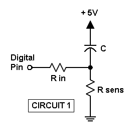
The digital pin is first set to Output mode and made high to discharge capacitor C through Rin, which is typically 220 ohms and acts simply as a current limiter. After a time to insure that C has been adequately discharged, the digital pin is set to Input mode and timing begins. An input pin has a very high effective resistance (over 100 Megohms), so it simply "observes" the voltage at the junction without affecting it.
The discharged capacitor initially behaves like a short circuit, so Rsens starts at +5 V, and the digital input is read as a logic high. As the capacitor charges up, it acts like an increasingly high resistance in series with Rsens. This means the voltage across Rsens continually decays, until it reaches the falling input threshold voltage where it is detected as a logic low. The time to reach that state from the initial logic high is then recorded.
To find Rsens from the time t, use Rsens = t * K / C, where K is a constant that depends on the starting voltage (5 V) and the falling threshold voltage (a bit under 2.5 V). While in principle the value of K can be computed, it is better to measure it directly since the threshold may vary from device to device.
In fact, since C is also a constant whose value may not be known to high precision, it is best to roll that into K so you'd use Rsens = t * K. To determine K you would measure Rsens with a precision meter, or substitute a precision resistor temporarily. Then K = Rsens / t.
An alternative circuit can be used which has both Rsens and C grounded (Circuit 2):
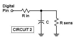
Perhaps surprisingly, this uses the exact same logic and math as Circuit 1, and gives the same readings, even though its actual operation is different. Just as above, the digital pin is put into Output mode and held high before timing begins, except here C is being charged instead of discharged. Then the pin is switched to Input and timing begins, only now the voltage across Rsens is the same as that across C, which is being discharged through Rsens. This circuit uses the same K value as Circuit 1, since in both cases the falling threshold is used.
Another alternative (Circuit 3) uses the rising threshold, and hence a different K value, though the math is otherwise the same:
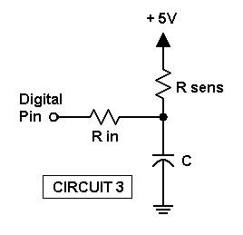
This simply reverses the positions of C and Rsens compared to Circuit 1, and might be preferable if, for some reason, your sensors need to have one terminal at +5 V. It uses a reversed logic sequence from the previous two circuits, such that in the initial Output mode the pin is set low to discharge the grounded C, then with the pin set to Input the time to reach the rising threshold is measured as C charges through Rsens.
You can use these same three circuits to measure variable capacitance sensors using a fixed resistance. Again, the math is the same, and you'd determine K the same way, with known resistor and capacitor values.
NOTE that regardless of the circuit you use, the linearity drops off severely as the Rsens value is reduced toward Rin. Consider Circuit 3 above during the initial Output low mode, when C is supposed to be discharged through Rin. With Rsens connected to +5 V it forms a voltage divider with Rin; if (for example) Rsens has a value equal to Rin (220 ohms) then the voltage at C can never go below +2.5 V... almost the same as the threshold voltage. So when timing starts, it reaches threshold almost immediately. The same voltage divider issue arises with the other circuits as well.
At larger Rsens values the divider voltage becomes smaller, making this less of a problem. 10K is a good lower limit to maintain linearity. For example, with a 10 microfarad C and 220 ohm Rin we get the following times (rounded) with 1% tolerance resistors:
    Rsens           Time         Time/Rsens
      1M           10900000         10.9
    100K            1080000         10.8
     10K             103000         10.3
      1K               7700          7.7
     300                750          2.5
     200                100          0.5
     100                  8          0.08
Due to internal delays and the 4 microsecond resolution of the Arduino timer, the lowest time that can be read is 4 or 8 microseconds. So the above reading of 8 microseconds with 100 ohms is effectively zero.
Given the above issue, one way to get accurate measurements at small resistance values is to simply add a fixed series resistor. With 10K in series, you can easily read down to 100 ohms with excellent linearity. Random variability between readings limits lower resistance measurements, but this can be overcome by averaging multiple readings.
IMPORTANT: Because RCtime involves waiting for a pin to change state as a capacitor charges or discharges to the pin's threshold, you should take precautions to prevent it waiting indefinitely due to a disconnected or defective sensor. This can be done with the same Wait timeout command that the 0xF1 Burst Acquisition (scope) uses to prevent waiting indefinitely for a missing trigger event. Include the Wait command before the 0xFC RCtime command:
Port=$(hF0) + "W" + $w(15625) ;Wait timeout = 1 sec
This way if one or more pins never reach threshold, the RCtime command will still return in 1 second (or whatever you specify) without hanging. Note that you must make sure that the Wait value is longer than the expected timing measurement. In the above table a Wait timeout of more than 10 seconds was needed for the 1M resistance, and more than 1 second for 100K.
The 0xFC function supports measurements on up to 6 pins simultaneously. They may be any or all of digital pins 2-7, and they must all use the same logic sequence. This means that they all must use grounded Rsens (Circuit 1 or Circuit 2, or a mix) or they must all use Circuit 3 with Rsens connected to +5 V.
After the 0xFC command byte, the next byte is the bitmap of the pins to be used. Only bits 2-7 are used for this, while bits 0 and 1 are control flags: Setting bit 1 indicates that the Rsens-high Circuit 3 will be used, while setting bit 0 high indicates that the timing will be in counts instead of microseconds.
Traditionally, RCtime code has functioned by counting the number of passes through a loop that waits for the logic threshold. That approach may give better resolution when only a single pin is being monitored, and especially when there are no background interrupts as required by the Arduino micros() function. But with the default interrupts the micros() approach is better, so always set bit 0 low to use microseconds.
Following the bitmap byte is a 2-byte word specifying the initial discharge (or charge) delay in microseconds. That should be at least five Rin * C time constants, where Rin is in ohms and C is in farads. However, ohms times farads gives seconds, so if you use the more common microfarads instead, the result will be in microseconds as needed for entry here.
So for example if Rin is 220 ohms and C is 0.001 microfarads their product would be 220 * .001 = 0.22 microseconds, and 5 times that would give 1.1 microsecond. But unless you want to take readings as fast as possible, you may prefer to use 1000 microseconds. That would cover all C values up to nearly 1 microfarad.
Command Example: If you are using pins 3 and 4 with either of the grounded Rsens circuits (1 or 2) and a 1000 microsecond discharge delay, the overall command would be:
Port=$(hFC) + $(b00011000) + $w(1000)
To allow very long discharge delays for very large C values, the number of milliseconds can be entered, as a negative value. The above example of 1000 microseconds is equivalent to 1 millisecond, so -1 could be entered instead of 1000:
Port=$(hFC) + $(b00011000) + $w(-1)
After you give the command string, you must fetch the return values. The initial return consists of a byte whose low nybble holds the total number of pins requested, followed by a 4-byte long holding the microseconds (or loop count) for the first pin to reach threshold. The initial read uses Daqarta's Port?5 to read all 5 bytes at once, as shown below:
U0=Port?5           ;U0=time or count, also sets Port?c
UC=Port?c           ;Num chans (pins) from above Port?5
Then you can read any additional pin values, up to the total UC. Pin values are stored in ascending time order, just as they are acquired. If all pins use the same capacitor values, then the pin with the lowest Rsens when RCtime runs will be the first to reach threshold, with pins having progressively higher Rsens being stored progressively later.
This means that the storage order is unrelated to the pin number, so a separate bitmap is stored for each time (or count) value. There will be only a single bit set in the bitmap, which tells which pin the value applies to.
Time (or count) values are stored in longAr[0]-[5], and bitmaps in intAr[0]-[5]. The longAr[0] value is the one returned in the initial read as U0 above. The intAr[0] bitmap for this value shows which pin it is for and must be read separately, as do any additional pin values and bitmaps.
To read intAr[0] into Daqarta variable Q0, you first send a read command to specify which DaqPort variable to read, then you read the returned value into the Daqarta variable:
Port#D1=h80            ;Request intAr[0]
Q0=Port?2              ;Read 2-byte integer into Q0
The next-highest value will be in longAr[1] and its map in intAr[1]:
Port#D1=h91            ;Request longAr[1]
U1=Port?4              ;Read 4-byte long into U1
Port#D1=h81            ;Request intAr[1]
Q1=Port?2              ;Read 2-byte integer into Q1
If a timeout occurs before all UC pins have reached threshold, their bitmaps will have no bits set, and their timer values will be very large (corresponding to the number of microseconds in the specified Wait timeout value).
You can read the number of pins that failed from intAr[7], here stored in Daqarta variable Q7:
Port#D1=h87                ;Request intAr[7]
Q7=Port?2                  ;Save as timeout count Q7
Note: You can convert a single-bit bitmap to a pin number by taking its base-2 logarithm via log2(), as in:
UN=log2(Q1) ;Bitmap to pin number
However, if the bitmap is empty due to a timeout from a failed sensor, the log2() operation returns a maximally negative value of -2^31 = -2147483648.
The Arduino_RCtime macro mini-app can continuously monitor up to 6 pins and display resistance or capacitance values, using any of the above circuit schemes. It includes calibration features and a selectable display time constant.
A simpler example is given below. It displays microseconds for two pins, but not continuously; it just shows the current values each time it is run. If you are creating your own custom code you may want to study and modify this first.
Posn#0="Ardu"          ;Specify Arduino only
Posn#1=0               ;Device count, 0 = first found
@_ComDev_Scan          ;Find and open device port

Mtr0="Waiting for RCtime..."
Port=$(hF0) + "W" + $w(15625)      ;Wait timeout = 1 sec

;RCtime on pins 3&4, Rsens grounded, read usec, delay 1000 usec:
Port=$(hFC) +$(b00011000) +$w(1000)
U0=Port?5              ;U0=initial pin time, also sets Port?c
UC=Port?c              ;Num chans (pins) from above Port?5

Port#D1=h91            ;Get next pin time
U1=Port?4

Port#D1=h80            ;Get initial bitmap
Q0=Port?2
Port#D1=h81            ;Get next bitmap
Q1=Port?2

Port#D1=h87            ;Timeout count
Q7=Port?2

;Show bitmaps, times, fails, and total pins:
Mtr0="    Pins      Time, us" +n _
    +Q0(b) +"  " + U0 +n _
    +Q1(b) +"  " + U1 +n _
    +Q7 +" Fail      " +UC +" pins"

Port#O=0               ;Close the device port
Multi-Pin Digital Write and pinMode:
    Command Byte 0: 0xFD
    Command Byte 1: Mode (see below)
    Command Byte 2: Data byte to write, or PORTD if word mode
    Command Byte 3: Second data byte PORTB if word mode
    Returns: None
The 0xFD command allows writing to multiple digital pins at the same time. Using the Atmel ATmega328P chip terminology, pins 0-7 are port D (PORTD), and pins 8-15 are Port B (PORTB). Note that since pins 0 and 1 are used by the serial port, and pins 14 and 15 are not available for normal use, the 0xFD command ignores attempts to change these.
The 0xFD command family can write to either port, or to both at once, depending on the low nybble of the Mode byte (the next byte after 0xFD):
Mode byte, low nybble:
    0 = PORTD
    1 = PORTB
    3 = Both
The high nybble of the Mode byte allows different types of writes:
Mode byte, high nybble:
    0 = Direct write, unmasked
    1 = Selected pins to INPUT
    2 = Selected pins to OUTPUT
    4 = Selected pins to INPUT_PULLUP
    8 = Write masked data
    C = Set masks
A masked write (high nybble = 8) allows certain data bits to be ignored by clearing the corresponding bits in separate mask bytes, which must be set first (high nybble = C) and can then be used until explicitly changed. Note that the masks always have bits 0, 1, 14, and 15 cleared so those pins will be ignored.
A direct (unmasked) write (high nybble = 0) writes the data byte(s) as given, with the usual exception of pins 0, 1, 14, and 15 which are always masked.
Note: Before a pin can be used for output, it must be configured as such by setting the pinMode to OUTPUT. This can be done for individual pins via the 0xD0 Digital Output / Mode Set functions, or for multiple pins using 0xFD with its Mode byte high nybble set to 2.
Similarly, you can set multiple pins to INPUT with 0xFD with the Mode high nybble set to 1, or to INPUT_PULLUP with it set to 4.
Complete command series, values in hex:
    FD, 01, <byte>  Direct write to PORTD, unmasked
    FD, 02, <byte>  Direct write to PORTB, unmasked
    FD, 03, <word>  Direct write to PORTD and PORTB, unmasked
    FD, 11, <byte>  Set PORTD pins to INPUT
    FD, 12, <byte>  Set PORTB pins to INPUT
    FD, 13, <word>  Set PORTD and PORTB pins to INPUT
    FD, 21, <byte>  Set PORTD pins to OUTPUT
    FD, 22, <byte>  Set PORTB pins to OUTPUT
    FD, 23, <word>  Set PORTD and PORTB pins to OUTPUT
    FD, 41, <byte>  Set PORTD pins to INPUT_PULLUP
    FD, 42, <byte>  Set PORTB pins to INPUT_PULLUP
    FD, 43, <word>  Set PORTD and PORTB pins to INPUT_PULLUP
    FD, 81, <byte>  Write masked data to PORTD
    FD, 82, <byte>  Write masked data to PORTB
    FD, 83, <word>  Write masked data to PORTD and PORTB
    FD, C1, <byte>  Set maskD
    FD, C2, <byte>  Set maskB
    FD, C3, <word>  Set maskD (low) and maskB (high)
EXAMPLES:
Direct write of binary 10101100 to pins 2-7, assuming previously set to OUTPUT mode. Note that these pins are all in PORTD, so we use command mode 01 and send a single byte of data:
Port=$(hFD) +$(h01) +$(b10101100) ;Direct write to PORTD
Direct write of hex 3AE6 to pins 2-13, assuming previously set to OUTPUT mode. These pins include PORTD and PORTB, so we use command mode 03 and send a word:
Port=$(hFD) +$(h03) +$w(h3AE6) ;Direct write to PORTB and PORTD
INPUT mode set on pins 8 and 10 only. These are in PORTB, so we use command mode 12. These pins are selected via binary 00000101 since we only send a high byte for bits 8-15, not the low bits 0-7 (PORTD):
Port=$(hFD) +$(h12) +$(b00000101) ;PORTB pins to INPUT
OUTPUT mode set on pins 3, 4, 8, and 10 only. Since this includes PORTD (0-7) and PORTB (8-15) we use command mode 23 and send a word of data:
Port=$(hFD) +$(h23) +$w(b0000010100001100) ;PORTB and PORTD to OUTPUT
INPUT_PULLUP mode set on pins 3 and 4 only. These are in PORTD, so we use command mode 41 and send a byte holding the selected bits:
Port=$(hFD) +$(h41) +$(b00011000) ;PORTD pins to INPUT_PULLUP
Masked write of pins 8 and 10. Let's suppose that we are working with a variable US that holds the current states of all bits 0-15, and we don't want to have to consider any of the other bits, or which port they are in. We first set maskB and maskD using command mode C3 and send a word mask:
Port=$(hFD) +$(hC3) +$w(b0000010100000000) ;Set maskB and maskD
Then we send the data to be written to these pins. Let's say that we want to write a 0 to pin 8 and a 1 to pin 10. We can first modify US to reflect this, starting with clearing bit 8 by ANDing US with the NOT of 2^8:
US=US & ~2^8 ;Clear bit 8 in US
Then we set bit 10 in US by ORing with 2^10:
US=US | 2^10 ;Set bit 10 in US
Finally we perform the masked write, using control mode 83 and sending US as a data word:
Port=$(hFD) +$(h83) +$w(US) ;Masked write of PORTB and PORTD
Event / Race Timer:
    Command Byte 0: 0xFE
    Command Byte 1: Trigger pin in low nybble, flags in high
    Command Byte 2: Signal pin in low nybble, flags in high
    Command Byte 3: Event pin, else multi-pin bitmap
    Command Byte 4: Optional false-start detection pin
    Returns: Total pins hit byte, initial hit time/count longAr[0]
             Multi-pin times in longAr[1] to [5], read via 0x91 to 0x95
             Multi-pin maps in intAr[1] to [5], via 0x81 to 0x85
The 0xFE command performs various types of timing, including single-pin event (pulse) width or cycle duration, as well as multi-pin "race" timing on up to 6 pins.
Following the 0xFE command byte are Trigger, Signal, and Event bytes. Each of these bytes refers to a pin number, or to multiple pins for the Event byte, and also has separate bits that act as option flags.
Trigger byte: The low nybble of this byte holds the Trigger pin number, which may be 2-13, or else 0 or 1 if no Trigger is to be used. The Trigger may be an external signal such as a switch closure that indicates timing is ready to proceed. For example, in a multi-event race timer the Trigger may indicate that all cars are aligned properly at the starting line. Alternatively, in a single-pin pulse width or cycle timer it may indicate the start of the pulse.
The high nybble of the Trigger byte holds option flags:
h10  Polarity active low if set, else active high
h20  Wait if not ready
h40  Enable mode, else Start mode
h80  False Start detection, requires command byte 4
If the Polarity bit h10 is set the Trigger event is a low state on the Trigger pin, otherwise the default is a high state to trigger.
If the Wait bit h20 is set, it means that no Trigger event will be accepted unless the opposite Polarity is detected first. With the default active-high Polarity the Trigger must be a rising edge that starts from a low state. If you give the 0xFE command when the Trigger pin happens to be high, nothing will happen until it goes low, then the Trigger will armed awaiting the next rising edge.
If the Enable bit h40 is set, the Trigger pin enables the timing, which starts when Event goes active and ends when it goes off. If the bit is clear, then the Trigger actually starts the timing, which ends when Event goes active.
If the False Start bit h80 is set, then the 0xFE command must include an extra byte to provide the pin number and polarity of the detector, which is only used for multi-event timing. The detector is typically a photodetector that monitors a light beam that passes across the starting line. If any contestant breaks the beam before the Trigger signal, a false start is declared and the race is aborted.
Signal byte: The low nybble holds the Signal pin number, which may be 2-13 or else 0 or 1 for no Signal. The Signal pin is an output that changes state to indicate that timing has started, such as after a Trigger event has been detected.
The high nybble of the Signal byte holds option flags:
h10  Polarity active low if set, else active high
h20  millisecond timing, else microsecond
h40  Multi-Event mode, else single event
h80  Hold-Off waits for all Event pins off before start
If the Polarity bit h10 is set the Polarity event is a low state on the Polarity pin, otherwise the default is a high state to drive the signal.
If the millisecond bit h20 is set, all reported times are in milliseconds instead of the default microseconds. Since the time readings are 32-bit integers, but always positive, the highest value is 2^31-1 or 2147483647. If this is microseconds, it is equivalent to 2147.5 seconds or 35.8 minutes. If it is milliseconds, it is equivalent to 596.5 hours. You probably won't need to time anything that needs this duration, but on the other hand you probably don't need microsecond resolution for soapbox derby or foot races.
The Multi-Event bit h40 specifies that the following Event byte will be a bitmap of event pins, otherwise it will hold a simple pin number for a single event pin.
If the Hold-Off bit h80 is set along with Multi-Event, then the function will wait for all Event pins to be off before starting timing.
Event byte: For single-event timing (Multi-Event bit h40 not set in Signal byte) the low nybble of this byte holds the Event pin number 2-13. The high nybble may have Polarity bit h10 set for active low, as for Trigger and Signal bytes.
If Multi-Event bit h40 in the Signal byte is set, then the Event byte is a bitmap of the pins to be timed. Up to 6 pins may be specified, which must be in the range of 2-7. If bit 0 is set, the polarity is inverted for all Event pins. If bit 1 is set, the function exits after the first event is detected (overall winner only), otherwise the function waits for all selected pin events to complete.
b00000001  Polarity active low if set, else active high
b00000010  Exit after first event (overall winner only)
bxxxxxx00  Contestant bitmap - any or all six pins 2-7
Timing Mode Usage Examples:
In these examples, we'll consider how to set variables UT, US, and UE to hold the Trigger, Signal, and Event bytes, respectively, for various timing uses. We'll assume that UP already holds the input pin number for single-pin timing. These variables will later be used in the actual 0xFE function call.
Measuring Period or Frequency:
Suppose you want to measure the period of one complete cycle of a square wave, such as from the start of a rising edge to the start of the following rising edge. (You could afterward compute frequency as the reciprocal of the period.) Using "active high" polarity (the default), you can consider the first rising edge to be the Trigger, and the following one to be the Event.
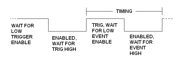
Since the command may arrive at any arbitrary time, including the midst of the high phase, we need to insure that we don't start looking for that rising edge until we have first found a low state. So the Trigger byte will need to have the h20 Wait bit set in the high nybble, with the low nybble holding the pin number. Note that the h40 Enable bit must not be set, so that timing will start when the Trigger is detected and end when the Event is detected:
UT=h20 + UP
The Signal byte can just hold a pin number, such as LED pin 13, with no high-nybble flags:
US=13
That assumes you want to measure period in microseconds; add h20 to the above to get milliseconds.
The Event byte should hold the same pin number as the Trigger byte, with no high-nybble flags:
UE=UP
The Arduino_Counter macro mini-app uses this setup when its variable UF is set to 2 for Period and Frequency mode.
Measuring Inter-Pulse Interval:
Note that the 'period' measured using the above setup doesn't need to be the period of a repeating waveform; this same setup could be used to measure the time between two pulses on the same input pin UP. The pulse widths should be no less than 10-20 microseconds, likewise for the minimum interval between them. The maximum interval can be 2147.5 seconds if US defaults to microsecond timing, or 596.5 hours if its h20 bit is set for milliseconds.
To measure the time between pulses on different pins, just use different pin numbers in UT and UE. Note that the Trigger is always assumed to come before the Event, so make sure your pins are connected accordingly.
You can use inverted polarity (active low) on either or both pins by setting bit h10 as desired. You may prefer this if the pulses are produced by momentary switch closures, since you can use INPUT_PULLUP mode so that a switch only needs to connect to ground when it closes. Note that most mechanical switches are susceptible to contact bounce, which can cause spurious pulses. Here, however, there will be no problems as long as the Trigger switch bounce is over before the arrival of the Event, whose bounce won't matter since the initial contact will end the timing operation.
Measuring Pulse Duration:
To measure the duration of a single pulse, set the Trigger byte UT to zero to disable it.
The Signal byte should hold the pin number of the LED (pin 13), or another pin as desired. You can add h20 to it to get millisecond timing.
The Event byte should hold only the input pin number, assuming you want to measure the duration of a high pulse. If you want to measure the duration of the low phase, add h10 to the pin number to specify inverse polarity.
The Arduino_Counter macro mini-app measures high pulse duration when its UF variable is set to 0, or low duration when it is set to 1.
Multi-Event (Race) Timing:
Consider a race with up to 6 contestants. These could be people or animals running a foot race, or real or model cars in a drag race, soapbox derby, or pinewood derby, or any sort of race-type situation with separate start and end points and no multiple laps. Each contestant must have its own detector at the finish line, which necessitates separate lanes.
Since multi-event mode 'contestant' pins must be in the 2-7 range, the Trigger pin is typically in the 8-12 range. Its h20 bit is normally set so that timing will wait for the trigger to change from inactive to active (rising edge, assuming bit h10 is not set for active-low mode). If the trigger is pin 11, you could use:
UT=h20 + 11
The Signal pin must have bit h40 set to specify that the following Event byte will be a multi-pin bitmap. Assuming the race will last less than 35.8 minutes, the h20 millisecond bit can be left clear to use the default microseconds. If the signal itself is LED pin 13, we get:
US=h40 + 13
The Event byte is now a bitmap where bits 2-7 represent contestant pins. Suppose there are only 2 contestants, on pins 2 and 3. In that case the Event byte could be:
UE=b00001100
You can set bit 1 (b00000010) to specify that the function should return as soon as the first contestant reaches the finish line, otherwise it will wait for the last one so all individual times can be reported.
You can set bit 0 (b00000001) to specify that all events will have active-low polarity.
With the above setup, all contestant pins must be off at the start or the function will return with a report of zero events.
Alternatively, you can set the h80 Hold-Off bit in the Signal byte, which will cause the function to wait for all contestant pins to be off before it starts looking for a trigger event. In this case you would probably want to set the Wait timer (see below) to catch the case where one or more contestant pins never go off.
To detect false starts, you can use a single photodetector that monitors a beam that runs across the starting line, to detect if any contestant breaks it before the trigger. The beam should be very narrow, such as a laser beam, so that forward motion by any contestant will break the entire beam.
To use this option, set bit h80 in Trigger byte UT, and also supply False Start byte UF after the Event byte in the 0xFE command. Setting bit h10 in UF will specify active-low polarity, otherwise it is assumed to be active-high.
Additional Setup Considerations:
Before actually giving the 0xFE command to start the timing, you need to set the Trigger and Event pins to INPUT or INPUT_PULLUP modes, as needed, and the Signal pin to Output. You should also set the Signal state to off, which would be 0 if you are using the default active-high Polarity, or else set it to 1 for active-low (bit h10 set in the high nybble).
Another important consideration before starting the timing is what happens if things go wrong, such as a Trigger or Event signal that never arrives, and thereby causes the function to hang while waiting for it. The solution is to use the same Wait timeout used for the Trigger of the 0xF1 Burst Acquisition (Scope) Function, and for the 0xFC RCtime function:
Port=$(hF0) + "W" + $w(-1) ;Wait timeout = 1 sec
Note that negative values signify seconds, while positive values are 64 microsecond tick counts at 15625 to the second.
Depending on what you are timing, you may need a larger Wait than 1 second. In the simplest (and probably most predictable) case of measuring the period of a rectangular wave, you might suppose that you just need to set the Wait longer than the longest expected period. But that's not long enough. Consider this square wave, with the various stages labeled:
If the 0xFE command arrives while the wave happens to be high, and timing has been set to start on a rising edge, then the function may have to wait for up to a full period for that rising edge before it even starts the timed measurement. Here the Wait should be set to twice the period to insure it doesn't time out during the measurement.
For multi-event race timing the Wait should be longer than the slowest expected race time. If you have also set Signal bit h80 to use Event Hold-Off, it will wait for all contestant pins to be off before starting to look for a Trigger to start the race. If it does not time out during that Hold-Off, the Wait will be restarted for the actual race.
Using The Event / Race Timer Function:
Now for the actual 0xFE command. Assuming variable UT holds the Trigger byte, US holds the Signal byte, and UE holds the Event byte, the overall command would be:
Port=$(hFE) + $(UT) + $(US) + $(UE)
For a multi-event race with false-start detection on pin UF, the high bit h80 of Trigger byte UT must be set to indicate that UF will be present:
Port=$(hFE) + $(UT + h80) + $(US) + $(UE) + $(UF)
In either case the return is 5 bytes, with the first byte holding the event pin number if it was a single-event measurement, or count of events if multi-event, and the following 4 bytes holding the elapsed time in microseconds (or millseconds, if requested via h20 in the high nybble of the Signal byte). You use Daqarta's Port?5 to read all 5 bytes at once, as shown below:
U0=Port?5           ;U0=time, also sets Port?c
UC=Port?c           ;Pin number or event count from above Port?5
For multi-pin events, you can then read any additional pin values, up to the total UC. Pin values are stored in ascending time order, just as they are acquired. This means that the storage order is unrelated to the pin number, so a separate bitmap is stored for each event. There will be only a single bit set in the bitmap, which tells which pin the value applies to.
Time values are stored in longAr[0]-[5], and bitmaps in intAr[0]-[5]. The longAr[0] value is the one returned in the initial read as U0 above. The intAr[0] bitmap for this value shows which pin it is for and must be read separately, as do any additional pin values and bitmaps.
However, note that the 0xFE function may not return promptly, even when it is working properly, since it has to wait for one or more events. For example, if you are measuring the period of a 1 Hz square wave (with timeout Wait set at 2 seconds per the earlier discussion), Daqarta's U0=Port?5 macro would wait patiently for the function to return. But that would block other activity like display updates, such as of a test signal being generated by the sound card, or a sound card input signal from the test response.
The "proper" way around this is to use multitasking, as is done in the DaquinOscope and DC Chart Recorder macro mini-apps. These use Custom Controls which take a fair amount of effort to set up, and which require use of macro subroutines such that the code is not all in one place for easy development or modification.
A crude-but-effective alternative is used by the Arduino_Counter and the Arduino_Race_Timer, each of which is completely contained its own single macro. This method allows continuous screen updates during the wait, by using serial port timeouts to check for returned data in a WHILE loop. If there is none, a display update takes place via a WaitTrace command before the next data check. (Note that since the actual race timing takes place in the Arduino, no event is missed during the display update.)
- Back to USB / Serial Communications Port Access
- Ahead to Arduino_Race_Timer Mini-App
- Daqarta Help Contents
- Daqarta Help Index
- Daqarta Downloads
- Daqarta Home Page
- Donate to Daqarta
Questions? Comments? Contact us!
We respond to ALL inquiries, typically within 24 hrs.INTERSTELLAR RESEARCH:
Over 45 Years of Innovative Instrumentation
© Copyright 2007 - 2026 by Interstellar Research
All rights reserved