Software for Windows
Science with your Sound Card!


Features:
Oscilloscope
Spectrum Analyzer
8-Channel
Signal Generator
(Absolutely FREE!)
Spectrogram
Pitch Tracker
Pitch-to-MIDI
DaqMusiq Generator
(Free Music... Forever!)
Engine Simulator
LCR Meter
Remote Operation
DC Measurements
True RMS Voltmeter
Sound Level Meter
Frequency Counter
Period
Event
Spectral Event
Temperature
Pressure
MHz Frequencies
Data Logger
Waveform Averager
Histogram
Post-Stimulus Time
Histogram (PSTH)
THD Meter
IMD Meter
Precision Phase Meter
Pulse Meter
Macro System
Multi-Trace Arrays
Trigger Controls
Auto-Calibration
Spectral Peak Track
Spectrum Limit Testing
Direct-to-Disk Recording
Accessibility
Data Logger
Waveform Averager
Histogram
Post-Stimulus Time
Histogram (PSTH)
THD Meter
IMD Meter
Precision Phase Meter
Pulse Meter
Macro System
Multi-Trace Arrays
Trigger Controls
Auto-Calibration
Spectral Peak Track
Spectrum Limit Testing
Direct-to-Disk Recording
Accessibility
Applications:
Frequency response
Distortion measurement
Speech and music
Microphone calibration
Loudspeaker test
Auditory phenomena
Musical instrument tuning
Animal sound
Evoked potentials
Rotating machinery
Automotive
Product test
Contact us about
your application!
Sound Card Distortion Measurement
Daqarta includes THD_Meter, THD_Meter_LF (Low Frequency), and IMD_Meter mini-app macros to automate distortion measurement and provide large (resizeable) readouts. Before using those, however, it is best to review the fundamentals here.
To analyze the distortion products, harmonic or inharmonic, produced by a system or device under test, you must first insure that the stimulus signal itself does not contain these same products. If it does, then they must be accounted for when viewing the output of the test system.
Connect the stimulus signal directly from the source to the input of the sound card (with suitable attenuation, if needed... see below) and observe the spectrum. You will need to use a window function to reduce leakage skirts from the FFT unless you carefully adjust the source frequency. Otherwise, the skirts may be much larger than the distortion components you are seeking. If you are using the Daqarta Generator to generate tones, the Lines option allows locking the tone frequency to a single spectral line without need for windowing.
If you see unintended frequency components at levels above the noise floor, you know there is a problem with the source or with the sound card. Sound cards often have gain stages ahead of the ADC that may exhibit saturation effects. In any case, if you can determine the source of the distortion you may be able to deal with it.
If your stimulus is a single sine wave frequency, you can try substituting with a lower-distortion source and see if the spectrum improves. If you can't obtain such a source, there are some other tricks you can try: Reduce the signal with a passive attenuator before feeding it to the sound card.
You can use a simple voltage divider made of 2 resistors.
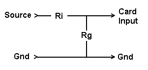
Connect one resistor from the source to the card input, and one from that junction to ground. If both resistors are equal (10 Kohms is a good value), the signal will be cut in half (-6 dB). If the distortion is coming from the source, it should now be reduced along with the signal by the amount of the attenuation. If it is not reduced that much, the sound card is clearly at fault and is showing the equivalent of crossover distortion. But if it is reduced that much, the card can't be ruled out yet, since any saturation-type nonlinearity would be expected to produce less distortion at lower levels.
A much more elegant and effective test is to measure the intermodulation distortion of the sound card, since any system nonlinearities will show up there. This test requires two separate sources, which can be the Left and Right outputs of the Daqarta Generator, or two external oscillators.
The beauty of the IM test is that it is easy to create a signal with essentially no intermodulation distortion, even if the individual sources have relatively high harmonic distortion. The trick is simply to add the two sources together linearly, which you can do with a simple passive resistor network:
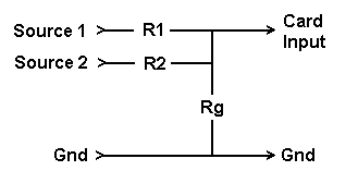
You can use 10 Kohms for each resistor... the value is not critical. Since resistors are very linear devices, they will create essentially no difference tones. And it doesn't matter how much harmonic distortion is present in each source, since that won't affect the inharmonic distortion which only arises when one tone interacts with another in a nonlinear system.
As noted previously, if you use the Daqarta Generator to create these separate tones, the Lines frequency step option can be used to insure that both output frequencies (and hence all distortion products) will fall exactly on spectral lines for easy measurements of low-level components.
The level of each source alone should be high, but within the linear input range. The resistor network with all values equal cuts each signal to 1/3 as it combines them, which insures that the sum will never exceed the input limits.
Set the two source frequencies such that difference tones will be easy to spot. For example, if the sources are at 500 and 700 Hz, the quadratic difference tone would be expected at 700 - 500 = 200 Hz and the cubic at 2 * 500 - 700 = 300 Hz. Neither of these is a harmonic multiple of 500 or 700 Hz, so if they are present they will stand out clearly from any harmonic distortion in either source.
On the other hand, if the sources were at 500 and 1000, the quadratic difference tone would fall at 1000 - 500 = 500 Hz and would thus be covered by the source tone, while the cubic would fall at 2 * 500 - 1000 = 0 Hz and would be hard to tell apart from harmless DC offset. In addition, all the upper difference tones would be 500 Hz apart and would thus fall on harmonics of the inputs.
There is an additional precaution: If either source tone has harmonics (or harmonic distortion components generated by the sound card) that exceed the Nyquist frequency, then when they are reflected down by aliasing they could end up at the same locations as the difference tones you wish to monitor. This shouldn't be a problem in an ideal sound card with an effective anti-aliasing filter, but with a real-world card you might want to check for this if you are trying to measure very low IMD levels.
The test is easy: View only one source at a time and look for unexpected peaks. For example, if a source is at 10000 Hz, it could have harmonic distortion harmonics at 20000, 30000, etc. If the sample rate is 48000 kHz, a 30000 Hz component will be reflected down to 48000 - 30000 = 18000 Hz. A 40000 Hz component will alias to 48000 - 40000 = 8000 Hz. A 50000 Hz component will alias to 48000 - 50000 = -2000 Hz which will appear at +2000 Hz after reflecting from 0. If you check each source separately and neither alone produces components at the difference frequencies, then proceed to turn them both on at once and look for intermodulation.
Alternatively, there is a simpler test for harmonics capable of interfering with intermodulation measurements: Apply both tones, then vary the sample rate and see what happens. Source and difference tones will be unchanged in frequency (though of course the frequency scale is changing, so they will move in unison on the screen), whereas any reflected harmonics will move independently.
One more potential problem: A source with a poor output stage might generate intermodulation via leakage from the other source back through the resistor network. If you see difference tones and this is suspected, try raising the level of one source and cutting the other by a comparable amount, so that the total signal to the sound card input is unchanged. If any measured distortion product increases or decreases by the same amount, then the problem was in one of the sources... the one whose level was changed in that direction.
Otherwise, if the sources are OK and the new overall level is the same, any distortion arising in the sound card should not change much. (This test and much more on the measurement of nonlinearity in ADCs was detailed in an article by Rathmell, Scott, and Parker in the October 1997 Journal of the Audio Engineering Society.)
If you see actual difference tones from these tests, you can assume that there is intermodulation in your sound card. If the distortion is smaller than what you are trying to measure in the test system, this may be acceptable. If not, try cutting both source levels (or the sound card sensitivity) in half. If that causes the distortion to drop by substantially more than 6 dB, you may still be able to use the card with careful attention to input levels. Otherwise, you may need to consider a new card.
If a new card is not an option there are "exotic" ways around this problem. They are cumbersome by comparison, but they illustrate general concepts for squeezing the maximum resolution from a measurement system. See Low-Level Distortion Analysis Techniques for details.
See also Distortion - Theory And Measurement
- Back to Distortion Orders
- Ahead to Sound Card THD Meter Mini-App
- Daqarta Help Contents
- Daqarta Help Index
- Daqarta Downloads
- Daqarta Home Page
- Purchase Daqarta
Questions? Comments? Contact us!
We respond to ALL inquiries, typically within 24 hrs.INTERSTELLAR RESEARCH:
Over 35 Years of Innovative Instrumentation
© Copyright 2007 - 2023 by Interstellar Research
All rights reserved