Software for Windows
Science with your Sound Card!


Features:
Oscilloscope
Spectrum Analyzer
8-Channel
Signal Generator
(Absolutely FREE!)
Spectrogram
Pitch Tracker
Pitch-to-MIDI
DaqMusiq Generator
(Free Music... Forever!)
Engine Simulator
LCR Meter
Remote Operation
DC Measurements
True RMS Voltmeter
Sound Level Meter
Frequency Counter
Period
Event
Spectral Event
Temperature
Pressure
MHz Frequencies
Data Logger
Waveform Averager
Histogram
Post-Stimulus Time
Histogram (PSTH)
THD Meter
IMD Meter
Precision Phase Meter
Pulse Meter
Macro System
Multi-Trace Arrays
Trigger Controls
Auto-Calibration
Spectral Peak Track
Spectrum Limit Testing
Direct-to-Disk Recording
Accessibility
Data Logger
Waveform Averager
Histogram
Post-Stimulus Time
Histogram (PSTH)
THD Meter
IMD Meter
Precision Phase Meter
Pulse Meter
Macro System
Multi-Trace Arrays
Trigger Controls
Auto-Calibration
Spectral Peak Track
Spectrum Limit Testing
Direct-to-Disk Recording
Accessibility
Applications:
Frequency response
Distortion measurement
Speech and music
Microphone calibration
Loudspeaker test
Auditory phenomena
Musical instrument tuning
Animal sound
Evoked potentials
Rotating machinery
Automotive
Product test
Contact us about
your application!
Sound Card Engine Crank and Cam Sensor Simulator Mini-App
- Introduction
- External Connections
- Background
- Overview
- DESIGN Mode Operation
- CRANK/CAM Select
- Scope X-Axis (Degrees / msec)
- Base Teeth and Gap/Extra Teeth
- Tooth Shape
- Tooth Width
- Start Phase
- Width/Phase Units
- Custom Profile List
- Simple Example
- CYP Example
- Dual-Cam VVT Example
- Single-Cam VVT Example
- Custom Profile and Tooth Shape
- Custom Profile Summary Window
- Show Full CRANK/CAM Rev
- Adding User Notes
- Create Arb
- SIMULATION Mode Operation
- Creating Stand-Alone Generator Setups
- Variable, Control, and Array Usage
- Engine_Sim Macro Listing
- _Engine_Ctrls Macro Listing
- _Engine_Deg Macro Listing
- _Engine_List Macro Listing
- _Engine_List_Info Macro Listing
- _Engine_Set Macro Listing
- _Engine_Wave Macro Listing
- _Dummy_Task Macro Listing
Introduction:
Daqarta includes an Engine Crank / Cam Sensor Simulator macro mini-app called Engine_Sim that allows you to test an Engine Control Module (ECM) or Engine Control Unit (ECU) without an actual engine present, using the Daqarta Generator to simulate the sensor outputs.
To run it, hit the F8 key followed by the E key, or hit CTRL+F8 to open the Macro Dialog and double-click on Engine_Sim in the Macro List.
Engine_Sim uses a Custom Controls dialog that allows adjustment of various parameters. You can open this Help topic by right-clicking anywhere in the dialog. (You can also open it by clicking on the Help button when Engine_Sim is selected in the Macro List, or in the Macro Edit dialog.)
Engine_Sim starts in DESIGN mode (button at lower right), in which you set the parameters for the engine you want to simulate. Then you use Create Arb (at lower left) to create the final design and save it to a file for later use. Toggling the DESIGN button to SIMULATION allows you to load that design, or any other you've created, and run it at any constant RPM, or smoothly cycle over a range or RPMs, or run an arbitrary RPM test schedule you create.
Engine_Sim changes Trigger and Decimate settings during operation, but restores them and toggles the Generator off when you exit via the OK or [X] buttons of the Custom Controls dialog. However, if you exit while in SIMULATION mode and while holding down any shift key (SHIFT, CTRL, or ALT) the Generator will keep running the simulation exactly as you left it, without restoring Trigger or Decimate settings.
External Connections:
Note that Engine_Sim starts with outputs muted so you can view the waveforms while designing your simulation, without hearing annoying whines from your speakers or headphones. When you are ready to connect to an ECM/ECU, hit the F9 key to open the volume slider dialog, unmute the outputs, and adjust volume as needed for your external circuitry.
You will need to determine ahead of time what sort of signal your ECM/ECU expects. This is typically done using an oscilloscope to monitor the sensor outputs on a running engine. You can use Daqarta for this, with caution; inductive sensor outputs can exceed the limits of sound card inputs. (See Input Range and Limiter Circuits.) You should also consider running Engine_Sim on a laptop computer with battery power only, or using a USB isolator with a USB card, to avoid possible grounding issues.
If you know that your engine uses simple inductive sensors (2-wire, no built-in electronics) you may be able to use direct connections between your sound card and ECM/ECU, as long as the sensors are normally connected to automotive ground. Again, consider using a laptop running on battery, or a USB sound card plus isolator, if you have any doubts about grounding issues.
Sound card outputs are typically less than 5 volts peak-to-peak. Inductive sensors may produce quite a bit more than that at high speeds, but that doesn't mean the ECM/ECU needs the higher voltages; it's typically just looking for zero crossings to tell where the teeth are, so the sound card output may be enough as-is.
Otherwise, you will need a transformer for isolation and voltage boost, and possibly an external amplifier if your transformer doesn't boost it enough.
Systems that use Hall-type 3-terminal sensors may need a DC Pulse Output Circuit for each sensor. However, the 2 Channel USB Plug-Type Sound Card subtopic under Simple Sound Card Unipolar DC Modification shows a super-simple alternative that should work with almost all 2-sensor (CKP, CMP) systems, and costs less than US $10. 3-sensor (CKP/TDC/CYP or VVT) systems can use the same approach, covered in Unipolar DC Outputs under the 5.1 Channel CM6206 USB Sound Card subtopic. That card is about US $25, and will of course also work for 2-channel systems.
Background:
A modern automotive engine has an Electronic Control Unit (ECU) or Module (ECM) that monitors and controls fuel injection, spark timing, and other functions. It needs to keep track of engine speed and crankshaft and camshaft positions, which it does via sensors that monitor the passing of teeth on special gears or "wheels". The CranK Position sensor is abbreviated CKP, and the CaM Position sensor is CMP.
A typical scheme uses a gear with a missing tooth. The sensor outputs a pulse as each tooth passes, which the control unit can time and count. When an expected pulse is missing, it means that the crankshaft or camshaft is at the reference angle. All other angles can be determined by counting from this reference position.
Different engines, or the crank and cam on the same engine, may use different numbers of gear teeth, or may use gaps of more than one tooth. Or, instead of a gap, they may use one or more smaller, extra teeth. Often the cam may use only a single tooth.
Sometimes the "Cam" sensor is actually on the distributor shaft, which turns at the same speed as the cam (one revolution per full all-cylinders engine cycle). The "Crank" sensor may also be on the same shaft, with twice the nominal number of teeth to reflect the fact that the crank turns at twice the cam speed.
Instead of a CMP sensor, some engines use two separate "cam" sensors: The TDC sensor produces one pulse at the Top Dead Center position of each cylinder, while the CYP (CYlinder Position) sensor produces a pulse only at Top Dead Center of a single reference cylinder, such as #3 on a 4-cylinder engine.
Similarly, some engines use two sensors at different positions on a single cam, producing two cam waveforms that are offset by a certain number of degrees.
Engines with Variable Valve Timing (VVT) may also use separate cam sensors to monitor the angles of intake and exhaust cams, relative to the crankshaft. Certain single-cam VVT engines may use a single cam sensor.
Overview:
The Engine_Sim macro simulates the output of synchronized crank and cam sensors, where the cam turns at half the speed of the crank as in a normal 4-stroke engine. 2-sensor engines (CKP and CMP) can be simulated with an ordinary stereo sound card. 3-sensor engines (CKP/TDC/CYP or VVT) engines need a true multi-channel sound card. The 5.1 Channel CM6206 USB device (about US $25) is fine for this purpose.
Engine_Sim has separate Crank and Cam controls to set the base number of teeth (the number on a normal gear with no gaps or extras), the number of missing or extra teeth, the general tooth shape, the relative width of the gear teeth, and the relative positions (Start Phase) of the crank and cam.
Alternatively, you can load a Custom Profile List for the Crank or Cam (or both). This is a simple text file that gives the position and width of each tooth. The file does not include tooth shape information; that is determined by the current Tooth Shape control at the time the custom profile is loaded. You must use a Custom Profile List for Cam design on CYP and VVT engines.
At start-up, only the Crank controls are shown. You toggle the CRANK Design button to CAM Design to see and adjust the Cam controls. For CKP/TDC/CYP engines, you set the Cam controls for TDC (one pulse per cylinder). The reference pulse (slightly taller, at screen center) will become the CYP pulse via a separate toggle during Simulation mode.
The CYP pulse is typically at a different angle than the Cam (TDC) reference position, and may also be a different width than the TDC pulses. This situation is handled using a custom profile for the Cam, with a special first entry in the list describing the CYP pulse position and width.
Similarly, VVT engines use a custom profile to define the intake valve cam, with a special first entry specifying the base timing of the exhaust cam. Both cams are assumed to have the same sensor profile, despite the cams themselves having separate lobe shapes, with the sensor waveforms differing only in relative angular position. When Engine_Sim is later toggled to Simulation mode, you will be able to manually adjust the angles of each cam starting from these initial positions.
For VVT engines with only a single camshaft, a custom profile is still required. It will have a special first entry that indicates that the profile angle may be adjusted using a single manual control in Simulation mode.
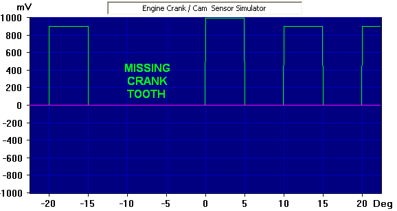
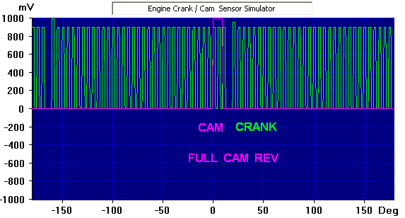
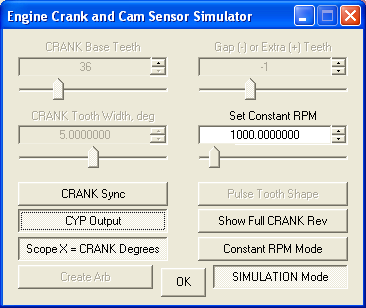
The default design is for a conventional non-VVT engine that has 36 Crank teeth with one missing, and one Cam tooth that is high for 10 degrees of cam revolution, from 160 to 170 Cam degrees. That aligns it over Crank teeth 33 and 34 on the second of the two crank revolutions. See Start Phase, below, for details.
The display shows the Crank profile in green and the Cam in violet, with the reference point (slightly taller pulse) near the center of the screen in a high-resolution view. Note that there is no Cam pulse visible, since it would be far over to the right at 320 Crank degrees, just before the second Crank reference pulse:
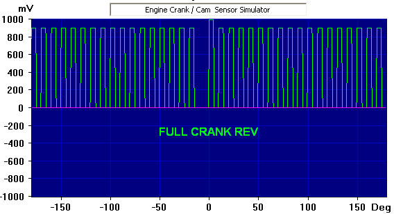
A Show Full CRANK/CAM Rev button compresses the view such that you see a full gear revolution, according to the current Crank or Cam Design mode: If Crank Design is active, the screen shows one revolution of the crank, again with no Cam pulse since it would be at 320 Crank degrees:
In Show Full CAM Rev, you see one revolution of the cam and two revolutions of the crank. The Cam reference is at 0 Cam degrees, which is 160 Cam degrees after the main (tall) Crank reference near the left, and 20 Cam degrees before the second (slightly shorter) Crank reference:
The Create Arb button saves the full Crank and Cam profiles as a two-channel Arb file, and you can then toggle the DESIGN Mode button to SIMULATION Mode to load and run it.
The Crank waveform will appear on the Left Out channel (green) with the Cam on Right Out (violet). These sound card outputs can then be used to simulate the corresponding sensor signals from a real engine, and used to drive an ECM/ECU module under test.
For 3-sensor engine simulations, the former Custom Profile button changes to CYP Output or VVT Output. If you click that and you have a true multi-channel sound card, the screen image won't change, but the Center channel of the card will produce either one CYP pulse at the reference TDC (Cam) location, or the VVT exhaust cam waveform. (The intake cam is on the normal Right Front Out channel.)
Alternatively, whether you have a true multi-channel card or only a stereo card, you can view the third channel on-screen by clicking the CYP Output or VVT Output button and noting that the wide Multi-Channel Outputs button becomes activated at the center of the Generator dialog. Clicking that opens a large dialog with a row of buttons for each of eight output channels, and columns for each of eight Generator streams. Ignore those, and click the Show All Raw Chans button at the lower left. Note that this only works if the Engine_Sim Show Full CRANK/CAM Rev button is off; otherwise the Show All Raw Chans button will be disabled and a message below it wil say "Toggle X-Axis Decimate OFF to enable."
This will show the third (Center) channel as a green dashed line, and will also space the three traces apart vertically on the display. You can adjust the amount with the Spacing control; you may also need to adjust the display magnification using the PgUp or PgDn keys. If your sound card is stereo only, this will allow you to see what you would get with a true multi-channel card.
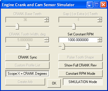
There are three speed simulation modes, set via the button just above the SIMULATION button: The default is Constant RPM, where the engine runs at the speed set via the Set Constant RPM control. The default speed is 1000 RPM, but you can change that default via a simple variable value in the macro script... see Custom RPM Test Schedules, below.
In Constant RPM mode the Scope X button is enabled at the lower left. When this is toggled on, the display X axis is shown in degrees instead of time units. If the CRANK Sync button (formerly CRANK Design) is active the axis will be shown in crank degrees; in CAM Sync mode they will be cam degrees.
If you click the Constant RPM button it advances to 600-6000 RPM Sine Cycle. In this mode the Set Constant RPM control changes to RPM Test Cycle, and the effective RPM slowly cycles between 600 and 6000 RPM and back according to the RPM Test Cycle duration control (10 second default). You can change the upper and lower RPM limits via simple variable values in the macro script. The Scope X button will be disabled until you return to Constant RPM.
Another click advances from Sine Cycle to Arbitrary Schedule Cycle to run a custom test schedule that you can create using the Arb_From_List macro mini-app. A default schedule is included that ramps from 600 RPM to 3000, holds, ramps to 6000, holds, and returns to 600 RPM over the RPM Test Cycle interval. As for the Sine Cycle, the Scope X button will be disabled until you return to Constant RPM on the next click.
For all of the above simulation modes, Daqarta's Frequency Counter is used in RPM mode to show the current speed. (Conversely, in DESIGN Mode the RPM is meaningless because the Generator is producing single-cycle waveforms at the fixed frequencies needed for the Create Arb process. Those Arbs are only run at variable RPM in the simulation modes.)
Note that Engine_Sim uses basic principles discussed in more detail under Engine Crank/Cam Sensor Simulation Principles and Creating Pulse-Train Arbs, but it's not neccessary to study or understand those in order to use Engine_Sim.
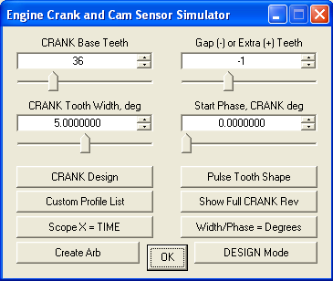
DESIGN Mode Operation:
    Base Teeth         Gap/Extra Teeth
    Tooth Width        Start Phase

    CRANK/CAM Select   Tooth Shape
    Custom Profile     Show Full Rev
    Scope X-Axis       Width/Phase Units
    Create Arb         DESIGN / SIMULATION
CRANK/CAM Select:
Engine_Sim starts in DESIGN mode as shown above, in which this button (at center left) defaults to CRANK Design. This allows you to set and adjust the number of teeth and profiles for the Crank gear. You can toggle the button to change to CAM Design at any time; the displayed values will be replaced with those for the Cam. The Crank values will remain unchanged internally while you adjust Cam settings (and vice-versa), and both the Crank and Cam waveforms will always reflect the current settings.
Later, if DESIGN Mode is toggled to SIMULATION Mode, the CRANK/CAM button changes to CRANK Sync or CAM Sync and controls the display synchronization so the crank or cam reference point is at the center of the screen.
In either DESIGN or SIMULATION modes this button also controls whether the Scope X-Axis button (below) shows crank or cam degrees.
Scope X-Axis (Degrees / msec):
By default Daqarta's main display shows the Crank and Cam waveforms with the X axis in time units, typically milliseconds (ms), for comparison to an external oscilloscope. But for many purposes it may be more useful to see degrees of revolution.
In DESIGN Mode, clicking the Scope X = TIME button toggles to Scope X = CRANK Degrees if the CRANK/CAM button is CRANK Design, or to Scope X = CAM Degrees for CAM Design.
Degree mode allows you to place the solid and dotted display cursors on selected waveform features, such as the rising and falling edges of a tooth, and read the absolute start and end degrees on the associated readouts, and the difference between them directly from the right-most readout (above the triangular delta symbol).
Note that the degrees shown there always match the current CRANK/CAM button state. Since one cam revolution spans two complete crank revolutions, a tooth width of 5 crank degrees will be read as 2.5 degrees in Cam mode.
This button works the same way in SIMULATION Mode.
Base Teeth and Gap/Extra Teeth:
The default Crank design is for a sensor system with a gear having a base of 36 teeth, but with one of those missing. The Base Teeth control is thus set at 36, and the Gap (-) or Extra (+) Teeth control is set at -1.
Set these controls to match the system you want to simulate. Base Teeth can be set from 1 to 142 teeth, and Gap or Extra Teeth from -3 to +3.
Although the ECM/ECU (under test or in a real engine) uses the gap or extra tooth as a reference mark (such as Top Dead Center on a particular cylinder), Engine_Sim uses a simple additional method to allow it to synchronize the display: It makes the tooth just after the gap (or the extra tooth) a little taller than the other teeth (100% of full-scale, versus 90%). This small difference will not affect operation of the ECM/ECU, but it allows Engine_Sim to sync the display reliably by setting Daqarta's Trigger Level to 97%: higher than all the teeth at 90% and the alternate Crank reference at 95%, but less than the main reference tooth at 100%. (Since the crank goes through two revolutions for each cam rev, Engine_Sim creates two full crank cycles, resulting in two crank reference teeth; the first one at 100% and the second at 95%. Triggering only on the first avoids the crank display jumping back and forth relative to the cam.)
Note that if you set the Gap/Extra control to 0, particularly for the Cam, the ECM/ECU on a 2-sensor (CKP and CMP) system would have no reference and could not operate properly. But Engine_Sim will still set one tooth larger so you'll still see a stable display.
3-sensor CKP/TDC/CYP systems typically do use Gap/Extra set to 0 on the both the Crank and Cam designs. Note that here Cam will be the TDC output, with one pulse per cylinder, so Base Teeth in Cam design mode is set to the number of cylinders. The slightly-larger Cam reference tooth will become the CYP pulse when activated in Simulation mode, and will appear only on the Center channel of a multi-channel card as one pulse per cam revolution (two crank revolutions). (The CYP Output button will only be available if you have more than one Base Tooth in the Cam design.)
Tooth Shape:
Once the teeth settings are correct, set the desired waveform for the tooth shape by repeatedly clicking on the button marked Pulse if you want another shape. The waveform (and button label) will advance through FS Pulse, Sine, Triangle, Ramp, Square, and back to Pulse. (You can move through these options in reverse by holding SHIFT down while you click.)
Pulse is appropriate for most modern 3-terminal sensors, including Hall effect sensors as well as inductive sensors that include added threshold electronics. The Pulse waveform goes high while the tooth peak is passing, then goes to zero until the next peak; never negative. In principle this allows "extra wide" teeth, where the output stays high more than half the time. This is only possible on Pulse and FS Pulse, not the other waveforms where 100% is one full cycle. (See Tooth Width, below.)
However, note that although the display will show a waveform that switches between zero and a positive value, the actual sound card output is AC coupled such that the output swings above and below zero. So for ECM/ECU testing you'll need a simple DC Pulse Output Circuit to convert to 0-5 V or 0-12 V as required by your unit. See External Connections.
The FS Pulse (Full-Scale Pulse) waveform switches between negative and positive full-scale values. This gives a larger signal than the default Pulse, but more importantly it allows the super-simple (one resistor per output) approach discussed under Simple Sound Card Unipolar DC Modification to get closer to 0 volts. It will be very close to 0 for the 5.1 Channel CM6206 USB device (about US $25) that should work with almost all Hall-type (0-5 V) systems, and will most likely be close enough to 0 to work with a 2 Channel USB Plug-Type Sound Card that costs less than US $10.
Sine, Triangle, and possibly Ramp or Square are appropriate as-is for 2-terminal inductive sensors.
The Square, Sine, and Triangle waveforms are all similar, in that they have outputs that run between positive and negative values, padded with zeros when Width is less than 100%. (Note that the default is 50%.) This behavior is roughly analogous to the raw output of a passive inductive sensor, which produces an output voltage swing when a tooth peak passes by, then returns to zero.
The Ramp waveform is a special case. Like Pulse, it swings between positive and zero, never negative. At a Width of 100%, it looks like a sawtooth with a vertical leading edge and a linear decline to zero. Reducing Width narrows each sawtooth by appending a zero section to each tooth profile.
However, Ramp allows you to control the shape of the sawtooth for Crank or Cam by editing macro variables Ur and/or Qr at the start of the Engine_Sim macro. These control the percent of time the ramp is rising; at the default of 0 percent rise, the ramp jumps immediately to maximum at the start of the tooth, then linearly ramps down to zero. Setting 100 percent rise gives just the opposite, ramping linearly from zero to max, then snapping back to 0. At 50% there are equal rising and falling slopes and it looks like a positive-only Triangle wave.
After changing the Tooth Shape waveform there will be a slight pause for recalculation of the tooth profile, then you'll see the new waveform on the display. The normal waveform display shows a close-up view of the wave shape in the region surrounding the reference (gap or extra teeth). Click the Show Full CRANK/CAM Rev button to see a compressed view that shows all the teeth in a full revolution.
The internal codes for Tooth Shape, and the single-letter abbreviations used in the Create Arb proposed file name are:
    0   s   Sine
    1   t   Triangle
    2   r   Ramp
    3   q   Square
    4   p   Pulse
    5   f   Full-Scale Pulse
Tooth Width:
By default, the base width of each tooth is such that the specified number of Base Teeth would just fit around the circumference of the gear wheel. A typical "tooth" consists of equal peak and valley (high and low) portions, but some gears use narrower teeth, with wider spaces between them. You can control this via the Tooth Width control.
Note that for the Pulse and FS Pulse waveforms, Width refers to the portion of the wave that is high. For all other shapes, Width refers to one full cycle of the specified waveform.
Width is shown in degrees of Crank or Cam rotation by default. If you toggle the Width/Phase = Degrees button to Width/Phase = Percent, Width will be shown as a percentage of the base tooth width.
With the default of 36 Base Teeth, each tooth would be 360 / 36 = 10 degrees of rotation. The default Width for the Crank is 5 degrees, which is 50% of the base tooth width.
With the Scope X-Axis button toggled to CRANK Degrees or CAM Degrees depending on the current design mode, you can place the solid and dotted display cursors on the rising and falling edges of a tooth, and read the difference in degrees directly from the right-most cursor readout. Use the rising edges of two adjacent teeth to read the base tooth width.
When Width is less than 100% of the base tooth width, the remainder is filled with zeros. For the default Pulse shape (where 100% would be all high) a Width of 50% means the first half of the tooth is high and the second half is zero. The result is a square wave between 0 and the high level. For FS Pulse, a full-scale negative value is used instead of 0 for the "low" part of the pulse.
For Sine, Triangle, Ramp, or Square, a Width of 50% means the full cycle would be compressed into the first half of the tooth profile, with the remaining half at zero. A Width of 100% would mean a continuous waveform (except for missing Gap teeth).
Note that for a gear with only one tooth (such as a Cam) the base tooth width becomes the whole circumference. In the default Cam design the single Pulse tooth is 10 Cam degrees wide (actually 9.9999756) out of 360 degrees, so if you toggle to Width/Phase = Percent that becomes 10/360 or 2.7777710 percent.
Start Phase:
Note that Tooth Width does not center a narrower tooth by providing equal zero sections on each side. That can be done with the Start Phase control, which essentially rotates the entire gear (Crank or Cam) relative to the other's reference. You will be able to see the results on the waveform display, as the green Crank teeth shift relative to the violet Cam teeth. (In the default design with only one Cam tooth at 160 Cam degrees, you'll need to be in Show Full CAM Rev mode to see this relative change.)
Just like Width, you can toggle the Width/Phase units button between Degrees and Percent to change the control units.
As noted under Tooth Width, above, you can toggle the Scope X-Axis button from TIME to CRANK Degrees or CAM Degrees and use the display cursors to read the phase difference directly from the cursor readouts.
In Crank Design mode, increasing Start Phase delays the gear by the specified number of degrees, or by the percentage of one full Crank revolution. However, in this mode the Crank display is still centered on the start of its reference tooth (just after the gap, for example), so its profile (green) does not move. Instead the Cam profile (violet) appears to move to the left as Start Phase increases. As you to continue to increase it, the Cam reference will roll off the left end of the display and reappear on the right end. At 360 degrees, it will be back at the original Crank reference.
In Cam Design mode, the situation is reversed: The display is centered on the Cam reference, and increasing Start Phase appears to move the Crank profile to the left. Since a full Cam revolution is two revolutions of the Crank, setting Cam Start Phase to 180 degrees is the same as setting Crank Start Phase to 360 degrees... back at the original reference, except at the start of the second revolution.
To align the Cam start to a given Crank tooth number, first determine the base width, in degrees, of a single Crank tooth (independent of the actual Width setting). Since the full Crank gear is 360 degrees around, the default 36-tooth gear would have tooth positions every 360 / 36 = 10 Crank degrees. However, the Cam turns half as fast as the Crank, so divide that in half to get 5 Cam degrees per Crank tooth.
To shift the Cam reference by a given number of Crank teeth, multiply by the Cam degrees per Crank tooth. Assuming teeth are numbered starting from 1, subtract 1 from the target tooth number first. In the default design, the Cam tooth starts over Crank tooth 33, so the Start Phase is 32 * 5 = 160 Cam degrees. In general, for Crank target tooth N:
Cam Start Phase = N * 360 / (Crank base teeth) / 2
which simplifies to:
Cam Start Phase = N * 180 / (Crank base teeth)
Since there are two crank revolutions per cam revolution, you can set the Cam reference to start at a specified tooth in the second Crank revolution by adding 180 Cam degrees to the above. The change to the displayed profile will be inconspicuous; you'll typically need to have Show Full CAM Rev active to see anything, and then it will look the same except that the two Crank reference pulses, one at 100% and one at 95%, will switch positions.
Note that the Crank Start Phase setting works to oppose the Cam setting. For example, the default design has Crank Start Phase set to 0, and Cam set to 160 degrees. If you change Crank to 5 degrees, you can maintain the same overall design by adding half that number to Cam to get 162.5 degrees.
Width/Phase Units:
By default Engine_Sim uses Degrees for the above Tooth Width and Start Phase controls. If you toggle this button from Width/Phase = Degrees to Width/Phase = Percent, then those controls will show and accept entries that are a percentage of the crank or cam revolution, depending on the current CRANK Design or CAM Design state.
Please note that this is independent of the Scope X-Axis button being in Scope X = CRANK Degrees or Scope X = CRANK Degrees. The X axis never changes to percent.
Custom Profile List:
The normal Base Teeth and Gap/Extra Teeth, Tooth Width, and Start Phase controls assume that the gear or wheel has regularly-spaced teeth, except for the Gap or Extra reference tooth. However, some engines use more complex spacing, particularly for the cam. For such engines you can use a Custom Profile List, which is a simple text file you create with any text editor such as Windows Notepad, or a full-featured text editor like Notepad++ or PSPad, or even Daqarta's Notes.
The file consists of a list of one line for each tooth, each line consisting of a start position, a separating comma, and a width, all in degrees. A single revolution of 360 degrees is always assumed, whether for Crank or Cam use.
Note that the tooth start positions are given in absolute degrees relative to the start of the Crank or Cam cycle.
Simple Example:
Here is a simple example of a 4-tooth profile. The teeth are regularly spaced at 90 degrees apart, but the initial tooth (which is always regarded as the reference tooth) is 20 degrees wide while the rest are only 10:
    0,20       ;Ref tooth at 0 deg, 20 deg wide
    90,10      ;Rest 90 deg apart, 10 deg wide
    180,10
    270,10
CYP Example:
For CKP/TDC/CYP engines that have a CYP pulse at a different angle and/or width than the Cam (TDC) reference pulse, the Custom Profile List must specify the CYP pulse as the first entry in the list. To indicate that it is a CYP pulse and not the first of the TDC pulses, add 1000 to the position. Here's the CAM_CYP.TXT file used to create the Engine12f@0.000_4Yf.DQA design, both included with Daqarta:
    1355,20    ;CYP pulse at -5 deg, 20 deg wide
    0,10       ;TDC pulses every 90 deg, 10 deg wide
    90,10
    180,10
    270,10
An initial pulse with a position of 1000 or more will only be accepted in Cam design mode; it will just be ignored in Crank mode, and the next line will be treated as the initial Crank pulse.
In this Cam mode example, the initial position will have 1000 subtracted to give 355. This example also shows how to enter a negative position. Here the CYP pulse is 5 degrees before the reference TDC pulse at 0 degrees. Since a full rotation is 360 degrees, you subtract 5 from 360 to get 355. Important: Since this is a Cam design, these are Cam degrees; this CYP pulse is equivalent to 10 degrees BTDC (Before Top Dead Center) in typical engine specifications.
The CYP pulse is assumed to come from a Hall sensor and is therefore rectangular. The default shape is Pulse (0 to positive full scale). If you enter a negative width then Full-Scale Pulse will be used that runs from negative full scale to positive full scale. This may be helpful when converting the AC-coupled sound card output to a DC pulse to drive the ECM/ECU.
Dual-Cam VVT Example:
Engines with Variable Valve Timing (VVT) must also use a Custom Profile List. Those with separate intake and exhaust cams are presumed to use identical sensors and gears on each, even though the cams themselves are different. As with the CYP design, a special first line is used. Here is the CAM_VVT2.TXT file used to create the Engine36-1p@40.000_4Dp.DQA design, both included with Daqarta:
    1025, 2000     ;Exhaust cam profile starts at 25 deg
    40,18          ;Intake cam profile starts at 40 deg
    100,45
    160,75
    295,30
Like the CYP design, the start position has 1000 added to it, only here the remaining 25 means the exhaust cam profile starts at 25 degrees. Unlike the CYP the 2000 "width" is a special code that tells Engine_Sim to create a full cam output waveform on the sound card Center channel; do not change this value.
Other than the exhaust starting at 25 instead of 40 degrees like the intake in the rest of the list, the two profiles will be identical. In other words, since the exhaust starts 40 - 25 = 15 degrees before the intake, the effective exhaust list is the same as the intake list with 15 subtracted from each position:
  Intake:      Exhaust:
    40,18       25,18
    100,45      85,45
    160,75      145,75
    295,30      280,30
When this design is later run in Simulation mode, separate intake and exhaust controls will be provided, which will default to 40 and 25 degrees respectively. You can then change them as you wish in real time.
Single-Cam VVT Example:
For VVT engines that use only a single cam, the first line of the Custom Profile List must have a "start position" of 1000 (or more, excess ignored) and a "width" of exactly 1000. Here is the CAM_VVT1.TXT file used to create the Engine36-1p@40.000_4Sp.DQA design, both included with Daqarta:
    1000, 1000      ;Single-cam VVT code
    40,18           ;Initial position is 40 degrees
    100,45
    160,75
    295,30
When this is run in Simulation mode there will be only a a single VVT Cam Angle control, defaulting to 40 degrees.
Custom Profile and Tooth Shape:
Note that the Custom Profile file does not otherwise include tooth shape information. When Engine_Sim loads the file, it uses the current Tooth Shape setting and applies it to each non-CYP tooth in the list. For example, if Tooth Shape is set to Sine, then each tooth will be one cycle of a sine save, interpolated as needed to fit into the specified width for that tooth.
While this interpolation is taking place, you'll see a "Computing full rev profile..." message until the profile is actually in use, which may take a few seconds depending on the number of teeth. The Custom Profile List button is then re-labeled to show the name of the loaded file. For example, if the file was named MyCam.TXT the button will show MyCam, without the .TXT extension.
Custom Profile Summary Window:
In addition, you'll see a summary of the profile in a separate Custom Profile text window. It will list the file name, tooth shape, total teeth, and the reference (initial tooth) phase and width in degrees. The CYP phase and width are also included, as needed, or the exhaust angle for dual-cam VVT designs. You can drag this window to any convenient location. The default font size is set to 30 pixels by this line near the start of the Engine_Sim macro:
Mtr0="<F(30)" ;Default font for Custom Profile info
You can change the default by replacing the '30' with another font size. If you want to change the size while the window is displayed, you can drag its lower border or corner until you get the desired text size. Then toggle the Design button twice to resize and reformat the window using the new font with proper margins.
If you want to test the same general Crank or Cam profile but use a different tooth shape, toggle the filename button back to Custom Profile List, change the Tooth Shape selection, then toggle Custom Profile List back on and load the same file again.
When Custom Profile List is active, the normal controls for Base Teeth, Gap/Extra Teeth, Tooth Width, and Start Phase are disabled, but still show the same settings. The Tooth Shape control is also disabled to show that you can't change the shape while the custom profile is loaded; you have to reload for that. The Width/Phase = Degrees/Percent button is also disabled since Custom Profile List always assumes degrees.
When you toggle Custom Profile List off, those controls are re-enabled and operation immediately reverts to the profile specified by the control settings.
When you toggle between CRANK Design and CAM Design the Custom Profile List button changes to reflect the new mode. For example, if the Crank mode is not using Custom Profile, the button is off (up) and labeled "Custom Profile List". But if the Cam mode is using Custom Profile, the button will be on (depressed) and labeled with the file name, and the Custom Profile summary window will be shown.
Show Full CRANK/CAM Rev:
Toggling this button on compresses the waveform display to show one or more full revolutions of the crank or cam. This is especially useful in DESIGN mode, since that view normally shows a close-up around the reference tooth specified by the CRANK/CAM select button.
This button is also available in SIMULATION mode. Note, however, that when active it disables the Show All Raw Chans button in the Multi-Channel Outputs dialog until you toggle it off. That button allows you to view the Center channel in CYP or Exhaust VVT simulations. (Specifically, the internal signal that will be sent to the Center Out channel in a multi-channel sound card, even if your card is stereo-only.)
Adding User Notes:
At any time during the Design process, before clicking the Create Arb button (below), you may enter any notes or other data that you want to store with the design.
Enter these in the main Daqarta Notes window. The window can be scrolled to enter multiple lines of text, or you can click the small Notes button to the left of the window to show many more lines.
Whatever you enter will be appended to the Engine_Sim internal data that is inserted at the beginning of Notes when the Create Arb file is saved. That inserted data may push your entry below the bottom of the small Notes window during the file save preview, so you may not see it then. But when you later load the design in SIMULATION mode you will be able to scroll down to view it, or use the Notes button for the larger view.
Create Arb:
In DESIGN mode, Engine_Sim uses the Daqarta Generator running at a constant speed. To allow for variable speed, both with Engine_Sim in SIMULATION mode and for other simulations of your own, you must save the gear profiles as a stereo Arb (arbitrary waveform) file by clicking the Create Arb button.
Note that you should not click this button until you have set both Crank and Cam designs as desired, since they are always saved as a set. Any added notes must also be entered before this.
The Crank profile will be saved as the left stereo channel of the file, with the Cam profile on the right channel. When the file is loaded for SIMULATION mode, the Crank and Cam channels will behave as separate but synchronized Arbs. The file also includes the parameters needed by CYP or VVT designs to create a third signal (CYP or VVT Exhaust) when used with a multi-channel sound card.
The Save As dialog will show a default file name that indicates the main settings you have selected: Number of base teeth, gap or extra teeth, and shape for both Crank and Cam, plus the Cam phase. For example, the default Crank design has 36 Base Teeth with one missing (-1), it is a pulse Tooth Shape, the Cam Start Phase is 160 degrees, and it has a single tooth that is also a pulse shape; the file name will be Engine36-1p@160.000_1p.DQA.
If instead of a missing Crank tooth there had been an extra tooth, the name would have been Engine36^1p@160.000_1p.DQA. If there are no missing or extra teeth, there is no entry between the base teeth and the tooth shape: Engine36p@160.000_1p
Note that the Crank Start Phase is not included in the name and assumed to be 0. The Cam Start Phase is rounded to the nearest integer degree.
If you use a Custom Profile in your design, that info will appear as an added letter between the tooth count and the tooth shape. The four possibilities are:
    L  ;List (Crank or Cam)
    Y  ;CYP (Cam only)
    S  ;Single-cam VVT
    D  ;Dual-cam VVT
So if instead of that default design, a 4-tooth Crank profile list is used, such as the Simple Example under that topic, the name would be Engine4Lp@160.000_1p.DQA. Or if a 4-tooth Cam list is used for a CYP design, such as the CYP Example, it would be Engine36-1p@160.000_4Yp.DQA.
While the Save As filename prompt is awaiting change or confirmation, the Daqarta Notes area shows the design parameters on the first line, the proposed filename on the second, and any Custom Profile List file on the third. That's usually a Cam profile, but if the design includes a Custom Profile for the Crank, the third line will show that instead. The Cam profile will then be on the fourth line, below the three-line main Notes window, as will any user notes. With the Save As dialog waiting for a response, you won't be able to see those lower lines. If you want to insure that you see everything before saving the design, click on the little Notes button at the left to open a larger Notes area before clicking Create Arb.
A typical Notes display during Create Arb is shown here for the Dual-Cam VVT Example design, with the addition of labels for internal parameters in green for Crank and violet for Cam, including extra parameters for the Cam VVT design that would otherwise be zeros:
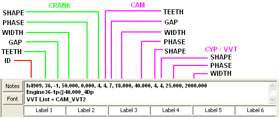
The first entry on the first line (h4909) is a code that identifies this as an Engine_Sim file. That's followed by the Crank parameters: Base Teeth, Gap or Extra (-3 to +3), Tooth Width (in percent of Base tooth width), Start Phase (in Crank degrees), and Tooth Shape (0-5 code... see table in that topic).
Next are equivalent parameters for the Cam, followed by special parameters for CYP or VVT designs:
Tooth Shape: Here 4=Pulse for this VVT design, redundant since VVT uses the shape set by the Cam Tooth Shape. (On the other hand, CYP designs will always be either 4=Pulse or 5=Full-Scale Pulse. See the CYP section under Custom Profile List.)
Start Phase: This is the degrees given on the initial line of a CYP or VVT Custom Profile with an added 1000 to identify that line. This will be the TDC pulse position on a CYP engine, or the default Exhaust valve degrees on a VVT which you can adjust during SIMULATION mode. (The main Cam Start Phase of 40.000 degrees is for the Intake valve.)
Width: For a dual-cam VVT design this is always 2000; for a single-cam VVT it is always 1000. For CYP designs this is the width of the TDC pulse in Cam degrees, which is the second entry on the initial line of the profile list. A positive value indicates Pulse, while a negative value is Full-Scale Pulse.
Feel free to change the Save As default file name to anything that is more meaningful to you, but it will be simpler if it starts with "Engine", as you'll see below. You can append extra text to the default name. Note that any name changes will not change the default name as shown in Notes here, but they will appear in that location when the saved file is later opened in SIMULATION mode.
If you hit the Cancel or [X] buttons in the Save As dialog, or hit the Escape key, no file is created and normal Design operation continues as before.
SIMULATION Mode Operation:
After saving the stereo Arb file, click on DESIGN Mode to toggle to SIMULATION Mode. This will allow you to select the file you've just created, or any previous Engine_Sim design file. By default the Open dialog shows all .DQA files that start with "Engine".
These example files are included with Daqarta:
Engine36-1p@160.000_1p.DQA is the default design with 36 crank teeth with one missing, pulse shape, single cam pulse at 160 degrees.
Engine30-2f@160.000_1f.DQA has 30 crank teeth with two missing, full-scale pulse shape, single cam pulse at 160 degrees.
Engine12f@0.000_4Yf.DQA is a CYP design having 12 crank teeth, none missing, full-scale pulse shape, cam reference zero degrees, 4 teeth with FS pulse shape. This simulates an engine with all sensors on the distributor shaft, where a 24-tooth wheel is used in place of a 12-tooth wheel on the actual crankshaft. When you load this in Simulation mode, the CYP Output option will be enabled. The Cam portion uses the CAM_CYP.TXT Custom Profile List included with Daqarta and shown in the CYP Example under that topic.
Engine36-1p@40.000_4Dp.DQA is a Dual-cam VVT design using the default Crank (36-1 teeth, Pulse shape) and the CAM_VVT2.TXT Custom Profile shown under Dual-Cam VVT Example.
Engine36-1p@40.000_4Sp.DQA is a Single-cam VVT design similar to the above, but using the CAM_VVT1.TXT Custom Profile shown under Single-Cam VVT Example.
If you hit the Cancel or [X] buttons in the file Open dialog, or hit the Escape key, Engine_Sim reverts to DESIGN mode. If you had been working on a design and changed any parameters from their defaults, your changes will still be there. The exception is that any Custom Profiles that had been loaded will be unloaded.
Otherwise, Engine_Sim loads the stereo Crank/Cam Arbs into the Daqarta Generator and reconfigures it to run at a variable speed. The Notes area shows the design parameters on the first line, the full path and actual filename on the second, any Custom Profile List file on the third, and any added User Notes below that. (You can scroll down to see those, or click the little Notes button on the left for an expanded multi-line view.)
Here is the Notes display for the same dual-cam VVT design mentioned above and shown in the Create Arb topic. The difference here is the expanded filename in the second line:
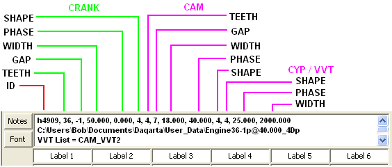
The actual filename is the proposed Engine36-1p@40.000_4Dp.DQA from Create Arb, or whatever name you may have changed it to, preceded by the full file path from the Save As operation.
All simulations use data stored in the first line of the Notes section to set up center-channel CYP or VVT output streams. The Base Teeth and Gap/Extra Teeth controls are disabled unless a VVT design is loaded, in which case Base Teeth becomes VVT Cam Angle for a single-cam VVT. A dual-cam VVT changes that to Intake Cam Angle, and changes Gap/Extra Teeth to Exhaust Cam Angle.
Tooth Width is disabled and Start Phase is replaced with Set Constant RPM. The CRANK/CAM Design button becomes CRANK/CAM Sync, but retains the same CRANK or CAM state. Tooth Shape is disabled, along with Create Arb.
Custom Profile List is disabled, unless a CYP or dual-cam VVT design is loaded, in which case that button toggles the Center output of the sound card and is labeled CYP Output or VVT Output as needed. The Width/Phase Units button is replaced with Constant RPM Mode.
The Scope X-Axis and Show Full CRANK/CAM Rev buttons retain the same states as in DESIGN mode.
Here is an example of controls for a normal engine simulation:
This is a CYP simulation:
A dual-cam VVT simulation:
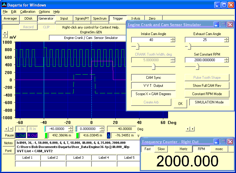
Here it is along with the full Daqarta display, as shown at the start of this Help topic:
SIMULATION Mode also automatically starts the Daqarta Frequency Counter in RPM mode to show the simulated engine speed. Note that Cyl (Cylinders) is at the extreme right end of the counter window, which was manually resized declutter the display. Engine_Sim always sets Cyl to 1; this is correct no matter how many cylinders the engine actually has, and no matter if CRANK Sync or CAM Sync is selected. This works because Cyl is normally set to twice the number of pulses per revolution, so with CAM Sync the counter sees one trigger pulse per two crank revolutions naturally. For CRANK Sync it works because the Crank channel actually consists of two crank revolutions, only one of which has a reference tooth at 100% level, high enough to exceed the trigger level setting of 97%. (Normal baseline teeth are at 90% and the non-sync Crank reference tooth is at 95%.)
When you toggle the SIMULATION Mode button off you will be back in DESIGN Mode, with the previous design running, with the exception that any Custom Profiles that had been loaded will be unloaded.
VVT Controls:
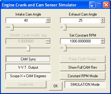
In a dual-cam VVT engine simulation the former Base Teeth control is replaced by Intake Cam Angle, and Gap/Extra Teeth becomes Exhaust Cam Angle. These allow manual adjustment over the full 360-degree Cam cycle. The Exhaust control default value is the degrees specified in the first line of the CAM_VVT2.TXT Custom Profile List used to create the Cam profile, which has 1000 added to it to indicate it's not the beginning of the main list. That value is 25 degrees in CAM_VVT2. The Intake control defaults to 40 degrees, the start of the main list:
    1025, 2000     ;Exhaust cam profile starts at 25 deg
    40,18          ;Intake cam profile starts at 40 deg
    100,45
    160,75
    295,30
Single-Cam VVT Simulation:
The first line of the Custom Profile is 1000,1000 to indicate a single-cam VVT engine. The Base Teeth control is replaced by VVT Cam Angle and its default value is the angle given in the next line, 40 in this CAM_VVT1.TXT example. There is no exhaust cam control; the normal Gap/Extra Teeth control is disabled:
    1000, 1000      ;Single-cam VVT code
    40,18           ;Initial position is 40 degrees
    100,45
    160,75
    295,30
RPM Mode:
In the default Constant RPM mode the speed is steady at the value given by the Set Constant RPM control. The default is 1000 RPM, but you can adjust the control between 600 and 6000 RPM. The default and limits are easily changed... see Custom RPM Test Schedules, below.
Clicking the Constant RPM button advances to 600-6000 RPM Sine Cycle mode, and the Set Constant RPM control changes to RPM Test Cycle, where the speed cycles smoothly between 600 and 6000 RPM and back over the indicated RPM Test Cycle time. The default is 10 seconds, which can be changed between 1 second and 1 hour (3600 seconds).
Clicking 600-6000 RPM Sine Cycle advances it to Arbitrary Schedule Cycle. Assuming RPM Test Cycle is set to 10 seconds, the built-in default schedule starts at 600 RPM, accelerates to 3000 RPM over the first 2 seconds, holds that for 2 seconds (to 4.00 seconds elapsed), accelerates to 6000 RPM in one second, holds for one second, then decelerates back to 600 RPM over 2 seconds and holds that for the remaining 2 seconds.
As with the Sine cycle, you can use the RPM Test Cycle control to stretch that to one hour, or reduce it to a ridiculously fast 1 second.
See Custom RPM Test Schedules below for details on how to easily create and install your own test schedule.
Custom RPM Test Schedules:
Parameters at the start of the Engine_Sim main macro can be changed to get different RPM ranges in SIMULATION Mode. The initial part of the macro looks like this:
    ;<Help=H4909
    UL=600                 ;Low Sine RPM / min Constant
    UH=6000                ;High Sine RPM / max Constant
    UR=6000                ;Max Arb RPM
    C=1000                 ;Default Constant RPM
    M=10                   ;Default RPM test cycle, sec
    ...
The default limits of the Constant RPM mode and the Sine cycle modes are between 600 and 6000 RPM, but you can change UL and UH to get different Low and High RPM limits.
Likewise, the default Arbitrary Schedule Cycle has a maximum RPM of 6000, but you can change UR to scale that up or down. Note, however, that this scales the entire schedule; for example, if you use UR=3000 then where the default schedule has a minimum of 600 RPM it will now be 300 RPM.
The C value sets the default Constant RPM, while M sets the default Sine or Arbitrary cycle time.
The default Arbitrary Schedule Cycle is an Arb file called RPM_Ramp_Arb.TXT. That file is loaded automatically by the EngineSim.GEN Generator setup used by Engine_Sim.
RPM_Ramp_Arb.TXT was created by the The Arb_From_List macro mini-app from a simple text list of times and RPM values called RPM_Ramp_List.TXT, which is in the Documents - Daqarta - User_Data folder. If you create your own file and give it the same name, it will be used instead:
    ;sec   RPM
    0.00   600     ;Start at 600 RPM, use elapsed time
    2.00   3000    ;Ramp up to 3000 at 2 secs
    4.00   3000    ;Hold at 3000 until 4 secs
    5.00   6000    ;Ramp up to 6000 at 5 secs
    6.00   6000    ;Hold at 6000 until 6 secs
    8.00   600     ;Ramp down to 600 at 8 secs
    10.00  600     ;Hold at 600 until 10 secs
Arb_From_List automatically scales the file so that the peak RPM is 100% of the Arb range, which gives 100% modulation when it is used to control the RPM via frequency modulation (FM). You thus set UR to tell Engine_Sim what RPM should be produced by 100% modulation. If you enter the same value that was used to create the Arb from your list, all the other schedule speeds will track as well.
Creating Stand-Alone Generator Setups:
Once you have a working design, and tested your simulation, you can use it to create a custom Generator setup (.GEN file) that runs that simulation on its own, without Engine_Sim or its Custom Controls dialog... you just load it and it runs your engine, your way.
Use Engine_Sim in SIMULATION Mode to get your desired simulation running. You can use the Custom RPM Test Schedules methods discussed above to create a specific Constant RPM, or a Sine Cycle with specified low and high RPMs, or an Arbitrary Schedule Cycle with default or custom speeds and times. Use the RPM_Test_Cycle control to set the duration.
Be sure to set the desired volume in the F9 control dialog, especially if you will be driving an ECM/ECU with this.
Then click Save Setup at the bottom of the Generator control dialog, and save your setup with a descriptive name. (Caution: Do not accept the default EngineSim name, since that setup is what Engine_Sim uses for start-up default settings, and it expects things to be set in certain ways.)
Whenever you load this setup the engine simulation will be running just like it was when you saved it.
Variable, Control, and Array Usage
The following summary of variable, control, and array usage is intended to aid in understanding the macro script operation. It can also help in modifying the script, including avoiding accidental re-use of critical variables.
Variables:
A       Wave sample value
B       Next wave sample for interpolation
C       Default Constant RPM
D       Working variable
F       Working variable
H       Tooth Height
K       Working variable
L       Working variable, deg/tooth
M       RPM test cycle, sec
P       Tooth Position
R       Working variable, Ramp rise
W       Working variable, tooth width
X       Working variable, tooth width
Q0      Working variable, min Cam teeth
Q1      Working variable, min Cam gap
Q2      Temp Cam gap
QG      Cam Gap
QI      Custom Profile start index
QL      File Load size
QM      Base Teeth Max
QP      CYP Pulse Shape (4=Pulse, 5=FS Pulse) else VVT = QW Cam shape
QT      Cam base Teeth
QW      Cam tooth shape
QZ      Temp Cam base teeth
Qd      CYP/VVT start phase, deg
Qr      Rise %, Cam Ramp wave only
Qs      Cam start phase
Qt      CYP tooth width, %, else VVT = 1000 or 2000
Qw      Cam tooth width, %
Qx      Temp Cam start phase
Qy      Temp Cam tooth width, %
U0      Working variable, min Crank teeth
U1      Working variable, min Crank gap
U2      Temp Crank gap
U6      Flag=1 if design changed, to restore later
U7      Btn7 loop count for Design restore on Simulate exit
UA      Working variable, wave index
UB      Working variable, Ramp wave index limit
UC      "RANK or "AM" for CRANK/CAM labels
UD      "deg" or "%" for labels
UE      Error flag
UG      Crank Gap
UH      High Sine RPM / max Constant
UI      Misc loop count
UJ      Misc loop count
UK      Misc loop count
UL      Low Sine RPM / min Constant
UM      Working variable, min teeth
UN      Working variable, _Engine_Wave points
UP      Wave sample number
UR      Max Arb RPM
US      Working variable, sample index
UT      Crank base teeth
UW      Crank tooth shape
UX      Working variable
UZ      Temp Crank base teeth
Ur      Rise %, Crank Ramp wave only
Us      Crank start phase
Uv      Working variable, tooth shape
Uw      Crank tooth width, %
Ux      Temp Crank start phase
Uy      Temp Crank tooth width, %

Custom Controls:
Ctrl0   Base Teeth, Crank/Cam  / Intake VVT adjust
Ctrl1   Gap/Extra Teeth, Crank/Cam / Exhaust VVT adjust
Ctrl2   Tooth Width, Crank/Cam
Ctrl3   Start Phase  / Set Constant RPM / RPM Test Cycle, sec
Btn0    Crank/Cam Design/Sync select
Btn1    Tooth Shape
Btn2    Custom Profile List / CYP or VVT Output
Btn3    Show Full Crank/Cam Rev
Btn4    Scope X = TIME or CRANK/CAM Degrees
Btn5    Width/Phase = Degrees/% / Simulation RPM (Const/Cycle/Custom)
Btn6    Create Arb
Btn7    DESIGN / SIMULATION select

Arrays:
Buf0    Misc text strings plus Custom Profile file names and values
Buf1    Values from Notes of opened Simulation file
Buf2    Phase values read from Custom Profile
Buf3    Width values read from Custom Profile
Str0    User Notes string
Str1    Design parameters string for Notes copy
Str2    Custom Profile List file names for Notes copy
Str3    Simulation file name (proposed and actual) for Notes copy
Engine_Sim Macro Listing:
This first sets the proper initial conditions, then loads the EngineSim.GEN Generator setup that has a default of 36 Crank base teeth with one missing, and one Cam tooth. Then it sets up and launches _Engine_Ctrls, a Custom Controls dialog with the needed controls, which runs until you close it.
Note that near the start of the listing Trigger Delay is set to negative 512 samples, which puts the trigger point in the center of the uneXpanded 1024-sample screen. This is important because the trigger point for missing-tooth simulations is the peak of the "sensor" output after the gap, so that if Delay = 0 then the gap would be unseen, prior to the left edge of the display.
Also note that Macro Array Buf0 is used to hold the ASCII equivalent of 6 characters which will be used by _Engine_Ctrls to build default Arb file names that encode the Tooth Shape waveform type, from 's' for Sine to 'f' for FS Pulse. The array index is the same as the Wave index for Sine through Pulse (0-4), while FS Pulse is at index 5.
Buf0 also holds the full names of each waveform in index positions 900 through 905, which are 900 more that the corresponding index values used above. These are used to label the Tooth Shape waveform selection button (Btn1).
In addition, Buf0 positions 910 through 920 hold text versions of the Gap/Extra Teeth values to be used in creating the default Arb file name. The text strings "-3" to "-1" are used as-is for Gap settings, while "" (no character) is used for a Gap of 0. However, Windows file names can't use the "+" character, so here we use "^1" to "^3" to encode +1 to +3 Extra teeth. Since the Gap/Extra parameter is not used with a Custom Profile List, it is replaced with an "L" (for List) in the relevant Crank or Cam portion of the default file name. Instead of "L", "Y" is used for a CYP design, "S" for Single cam VVT, and "D" for Dual cam (separate intake and exhaust).
Buf0 positions 90 through 96 will also hold parameters obtained from Custom Profile List files, and positions 100 through 115 will hold the names of any such files that are loaded.
An important part of the Engine_Sim setup is the creation of special MemArb arrays for the Crank and Cam waveforms. Each is created by calling the _Engine_Wave macro after setting the proper Crank or Cam tooth profile parameters, namely the target Arb number Ch, Tooth Shape wave type Uv, Width W, and (for Ramp waves) Ramp Rise percent R. _Engine_Wave is called later from the _Engine_Ctrls macro whenever wave type or Width are changed.
;<Help=H4909                ;Help invokes this topic
UL=600                 ;Low Sine RPM / min Constant
UH=6000                ;High Sine RPM / max Constant
UR=6000                ;Max Arb RPM
C=1000                 ;Default Constant RPM
M=10                   ;Default RPM test cycle, sec
Ur=0                   ;Rise %, Crank Ramp wave only
Qr=0                   ;Rise %, Cam Ramp wave only
QM=142                 ;Base Teeth, Max
Qt=0                   ;Default = no custom CYP/VVT file
Mtr0="<F(30)"          ;Default font for Custom Profile info

Close=
E.IF.Input=
    Input=0
ENDIF.
Spect=0
Sgram=0
Xpand=0
Decimate=0
XpandMax=4m
XpandMin=-4m
SmplSec=Smpl
Buf0="<=(0)"
Buf0[10]=TrigMode
TrigMode=Norm
Buf0[11]=TrigLevUnit
TrigLevUnit=0
Buf0[12]=TrigHyst
TrigHyst=0
Buf0[13]=TrigLevel
TrigLevel=97               ;Trigger on reference tooth only
Buf0[14]=TrigDelay
TrigDelay=-512             ;Center the reference on display
Buf0[15]=TrigSrc
TrigSrc=LO
Buf0[16]=TrigSlope
TrigSlope=Pos
Buf0[17]=Trig
Trig=1
FcountCyl=1                ;1 main crank/cam reference event/rev
Notes=                     ;Clear existing Notes
A.LoadGEN="EngineSim"
Ctrls="<<Engine Crank and Cam Sensor Simulator"
UC="RANK"                      ;Forms "CRANK" when added to fixed "C"
UD="deg"                       ;Changed to "%" as needed
Ctrl0="<<C" + UC(A) +" Base Teeth"     ;"CRANK Base Teeth"
U0=1                       ;Minimum Crank base teeth
Q0=1                           ;Minimum Cam base teeth
Ctrl0="<S(U0,QM)"              ;Max is 142
Ctrl0="<p(0)"                  ;Integer, no decimal places
UT=36                      ;Default 36 base Crank teeth
QT=1                           ;Default 1 Cam tooth
Ctrl0=UT                       ;Set Crank teeth control default
L=360 / UT                     ;Max tooth base Width, degrees
Ctrl1="<<Gap (-) or Extra (+) Teeth"
U1=-3                          ;Max Crank Gap = 3 teeth
Q1=0                           ;Max Cam Gap
Ctrl1="<S(U1,3)"               ;Range from max Gap to +3 Extra
Ctrl1="<p(0)"                  ;Integer only
UG=-1                          ;Default Crank Gap
QG=0                           ;No Cam Gap
Ctrl1=UG                       ;Set control with Crank Gap
Ctrl2="<<C" + UC(A) + " Tooth Width, " + UD(A) ;"CRANK Tooth Width, deg"
Ctrl2="<S(0,L)"                ;Width range 0 to max for this Base
Uw=50                          ;50% Crank default tooth Width
Qw=2.7777                      ;10 Cam degrees = 10/360 * 100 percent
Ctrl2=Uw/100 * L               ;Set control for Crank Width
Ctrl3="<<Start Phase, C" + UC(A) + " " + UD(A) ;"Start Phase, CRANK deg"
Ctrl3="<S(0,360)"
Us=0                           ;0 degree default Crank Start Phase
Qs=160                         ;160 deg Cam Start Phase
Ctrl3=Us                       ;Set control for Crank

Buf0[0]=115                    ;Letter 's' (Sine) for file name
Buf0[1]=116                    ;'t' (Triangle)
Buf0[2]=114                    ;'r' (Ramp)
Buf0[3]=113                    ;'q' (sQuare)
Buf0[4]=112                    ;'p' (Pulse)
Buf0[5]=102                    ;'f' (FS Pulse)

Buf0[900]#a="Sine"             ;For Tooth Shape wave button labels
Buf0[901]#a="Triangle"
Buf0[902]#a="Ramp"
Buf0[903]#a="Square"
Buf0[904]#a="Pulse"
Buf0[905]#a="FS Pulse"

Buf0[910]="-3"                 ;For Arb file name Gap/Extra teeth
Buf0[911]="-2"
Buf0[912]="-1"
Buf0[913]=""                   ;No Gap or Extra
Buf0[914]="^1"                 ;Extra teeth can't use "+" in file name
Buf0[915]="^2"
Buf0[916]="^3"
Buf0[917]="L"                  ;Custom Profile List
Buf0[918]="Y"                  ;CYP design
Buf0[919]="S"                  ;1-cam VVT
Buf0[920]="D"                  ;2-cam VVT

Btn0="C" + UC(A) + " Design"   ;"CRANK Design"
Btn0="<T"                      ;Toggle button type
Btn1="<M(5)"                   ;Multi-toggle for Shape waves 0-5
UW=4                           ;Crank wave 4 = Pulse
QW=4                           ;Cam wave = Pulse
Btn1=UW                        ;Default Crank wave
Btn1=""+Buf0[900+Btn1](a) + " Tooth Shape"     ;"Pulse Tooth Shape"

MemArb0#N=8                    ;Create MemArb0 with 8K (8192) samples
Uv=UW                          ;Set wave type for Crank (4 = Pulse)
W=Uw                           ;Set Width for Crank (50%)
R=Ur                           ;Set Ramp Rise (not used for Pulse)
Ch=0                           ;Set chan to fill MemArb0
@_Engine_Wave                  ;Build Crank tooth profile in MemArb0
L.0.Wave=Arb                   ;Set Left Stream 0 to use MemArb0
L.0.Arb0=1
L.1.Wave=Arb                   ;Set Left Stream 1 to use MemArb0
L.1.Arb0=1

MemArb1#N=8                    ;Create MemArb1 with 8K (8192) samples
Uv=QW                          ;Set wave type for Cam (4 = Pulse)
W=Qw                           ;Set Width for Cam (2.777%)
R=Qr                           ;Set Ramp Rise (not used for Pulse)
Ch=1                           ;Set chan to fill MemArb1
@_Engine_Wave                  ;Build Cam tooth profile in MemArb1
R.0.Wave=Arb                   ;Set Right Stream 0 to use MemArb1
R.0.Arb1=1
R.1.Wave=Arb                   ;Set Right Stream 1 to use MemArb1
R.1.Arb1=1

F=UH / 120                     ;Max freq for Sine RPM test
L.3.FMdev=F                    ;Set for Crank
R.3.FMdev=F                    ;Same for Cam
D=50 * UL / UH + 50            ;Offset for Sine RPM test
L.2.Offset=D                   ;Offset - Level = 100% * High / Low
L.2.Level=100 - D              ;Offset + Level = 100%
@_Engine_Set                   ;Build the Crank design
Btn0=1                         ;Force Cam mode
@_Engine_Set                   ;Build the Cam design
Btn0=0                         ;Restore Crank mode as default

Btn2="Custom Profile List"
Btn2="<T"
Btn3="Show Full C" + UC(A) + " Rev"    ;"Show Full CRANK Rev"
Btn3="<T"                              ;Toggle button type
Btn4="Scope X = TIME"
Btn4="<T"
Btn5="Width/Phase = Degrees"
Btn5="<T"
Btn6="Create Arb"
Btn6="<M"                      ;Momentary pushbutton type
U6=0                           ;Flag = no design changes yet
Btn7="DESIGN Mode"
Btn7="<T"
Buf0[50]=0                     ;Design mode

Task="_Dummy_Task"             ;Install Task
@_Engine_Ctrls=Ctrls           ;_Engine_Ctrls runs until close
Buf0[51]=Key?$                 ;Get shift key states
Mtr0=                          ;Close Custom Profile info
Task="-_Dummy_Task"            ;Uninstall Task
Notes=                         ;Clear Notes
DDiskTrig=0
DDiskPreset=0
Buf0#R=0                       ;Restore default X axis
IF.Buf0[50]=0                      ;Closing in Design mode
OR.Buf0[51]=0                      ;OR no shift key down?
    Gen=0                          ;Restore orig settings if so
    Decimate=0
    FcountDlg=0
    TrigLevUnit=Buf0[11]
    TrigLevel=Buf0[13]
    TrigHyst=Buf0[12]
    TrigDelay=Buf0[14]
    TrigSrc=Buf0[15]
    TrigSlope=Buf0[16]
    TrigMode=Buf0[10]
    Trig=Buf0[17]
ENDIF.
_Engine_Ctrls Macro Listing:
When any control is changed in the Custom Controls dialog launched by Engine_Sim, an event code is sent to the Ctrls variable and the _Engine_Ctrls dialog handler is activated to take appropriate action.
For example, if Base Teeth (Ctrl0, sending Ctrls code 0) is changed while Btn0=0 for CRANK Design mode, then variable UT is updated with the new Crank Base Teeth value. New limits are computed for the maximum Gap value for Ctrl1 and stored in U1. If the new Base Teeth is less than or equal to the current Gap setting, Ctrl1 and current Gap variable UG are forced to zero since the Gap must be less than the number of Base teeth. If the Degrees / Percent button (Btn5) is in Degrees mode 0, the Tooth Width setting is updated. Finally, a separate _Engine_Set macro (discussed later) is called as a subroutine to compute and set the proper Generator frequency, burst, and level parameters.
Alternatively, if Btn0=1 for Cam Design mode, variable QT for Base Teeth, Q1 for maximum Gap, and QG for current Gap are updated for Cam.
Base Teeth may be set from 1 to 142, and Gap/Extra may be set from -3 to +3, though (as noted above) Gap must be less than Base. If Gap/Extra is set to 0, the next Base tooth is used as the reference for the purpose of display alignment.
Ctrl2 (event code 2) controls Tooth Width for Crank or Cam, as discussed in that topic under Operation, above.
Ctrl3 (event code 3) controls Start Phase, as discussed in that topic under DESIGN Mode Operation, above, when Design mode is active. However, when SIMULATION Mode (Btn7) is active, this changes to Set Constant RPM or RPM Test Cycle, sec as discussed below.
Btn0 (event code 4) toggles between CRANK Design and CAM Design modes.
Btn1 (event code 5) is the Tooth Shape wave selection button. It is a multi-state pushbutton with a maximum state value of 5 (Full-Scale Pulse), set via Btn0="<M(5)" in the above Engine_Sim caller. The same control is used to set either Crank (UW) or Cam (QW) depending on the Btn0 Crank/Cam state, such that toggling Btn0 will change the current Btn1 state accordingly. Each click of the button advances Btn1 to the next wave index, automatically wrapping to 0 (Sine) after 5 (FS Pulse). The same wave type is set for both the main gear on Left Stream 0, and the reference teeth on Left Stream 1 and Left Stream 3, assuming Crank Design mode, or to Right Stream 0 and 1 for Cam.
Btn2 (event code 6) toggles the Custom Profile List button, which prompts you for the name of a Crank or Cam profile in list form. In Simulation mode, this button may change to CYP or VVT Output according to the first line of the Cam list.
Btn3 (event code 7) toggles Show Full CRANK/CAM Rev mode. When this button is off (default) in Crank mode, the display shows 1024 samples out of 8192 being used for the full Crank gear. To show them all, Decimate mode is toggled on with a Factor of 8. Trigger Delay is also increased by a factor of 8 (from -512 to -4096 samples) to keep the reference near the center of the screen.
In Cam mode the default display shows 1024 samples out of 16384 for the full Cam gear (which is two full Crank revolutions at 8192 samples each); Decimate is thus set to a Factor of 16 and Trigger Delay increased by the same factor (to -8192) to show a full Cam rev.
Btn4 (event code 8) toggles to Scope X = CRANK Degrees or Scope X = CAM Degrees when active, according to the Btn0 state. While Btn4 is active, toggling Btn0 will change the Btn4 label to match. This state persists when changing between DESIGN and SIMULATION modes (see below), except that it is disabled for Simulation using 600-6000 RPM Sine Cycle or Arbitrary Schedule Cycle.
Btn5 (event code 9) toggles between Width/Phase = Degrees and Width/Phase = Percent. It affects the units used for Tooth Width and Start Phase controls Ctrl2 and Ctrl3.
Btn6 (event code 10) is Create Arb, which uses Direct to Disk (DDisk) recording with the size preset to 16384 samples (maximum Arb size). A standard Windows Save As dialog is opened with the default file name encoding the number of Crank base and gap or extra teeth, as well as the Tooth Shape wave type and Cam Start Phase. The Notes area changes to show a list of parameters on the first line, followed by the above default file name on the second, then the names of any Custom Profile Lists in use, followed by any Notes you may have entered during for the current design.
Btn7 (event code 11) toggles DESIGN Mode to SIMULATION Mode, which completely changes the Generator setup. Instead of generating the raw waveform directly, it uses a stereo Arb file which you select from previous Create Arb files. The Left channel becomes the Crank Arb, where one 16384-sample cycle of the Arb is two revolutions of the Crank. The Right channel is the Cam Arb, where one 16384-sample cycle is a single Cam revolution.
SIMULATION Mode also changes Ctrl3 to Set Constant RPM, and Btn5, which defaults to Constant RPM but can be clicked to advance to 600-6000 RPM Sine Cycle or Arbitrary Schedule Cycle.
In addition, SIMULATION Mode changes Btn2 from Custom Profile List to CYP or VVT Output, but only if specified as one of these types via the code in the first line of the list originally used to create the design. Otherwise, the CYP/VVT Output button will be off by default.
The stereo Arbs are used as the Left Stream 3 waveform for the Crank, and Right Stream 3 for the Cam. The effective RPM is controlled by the "tone" frequency of these streams, where 50 Hz is 6000 RPM. Note that engine RPM is always Crank RPM, and the Crank Arb holds two Crank revolutions per Arb cycle. So when the Arb is running at 50 Hz, the Crank is effectively turning at 100 Hz. Since there are 60 seconds in a minute, this is 6000 RPM.
The actual Left and Right Stream 3 frequencies are controlled by Frequency Modulation from Left Stream 2. The Stream 3 frequencies are linearly proportional to the current value of Left Stream 2. That value is a constant in Constant RPM mode, since the Left Stream 2 waveform is ignored by setting its Level to zero, while the Set Constant Frequency value from Ctrl3 is used to set the Offset to a constant percentage of the full modulation range, and hence provide a constant RPM.
To do this, the Left and Right Stream 3 Tone Frequencies are at 0 Hz, meaning that with no frequency modulation there is 0 RPM. The FM deviation is set to +/-50 Hz for both streams, which means that when the modulation is +100% the frequency will be 50 Hz, which is 6000 RPM as noted above.
When Btn5 is clicked to advance from Constant RPM to 600-6000 RPM Sine Cycle, the Left Stream 2 Level is given a specific non-zero value which, together with a specific Offset, allows the slow Left Stream 2 output waveform (set by RPM Test Cycle from the new Ctrl3) to slowly drive the Stream 3 frequencies and thus smoothly cycle from 600 to 6000 RPM and back on a slow sinusoidal curve.
The FM Source for each stream is Left Stream 2, whose Tone Frequency is set by the inverse of the RPM Test Cycle, sec interval. That defaults to 10 sec, giving 0.100 Hz for the Tone Frequency. Note that while you can set the period as high as 3600 sec (1 hour), the frequency is then so low that the resolution is quite coarse.
Since FM Deviation is set so that 100% modulation gives 6000 RPM, to get the 600-6000 RPM range the modulator needs to go from 10% to 100%. The Left Stream 2 sine wave normally runs +/-100%, so the Level and Offset are set to 45% and 55% respectively. Thus when the wave is at its positive peak of +45%, the added 55% Offset gives 100% total. When it is at its negative peak of -45%, the added Offset gives 10%.
This use of a single modulation source stream makes it possible to easily change to something other than a constant or a sine wave to describe the engine speed schedule. You can change the Left Stream 2 wave to a triangle, or a ramp with different rising and falling slopes, or even a custom Arb controller file with separate idle, acceleration, cruise, and decelerate sections.
That latter is what you get by advancing Btn5 from 600-6000 RPM Sine Cycle to Arbitrary Schedule Cycle. That uses an Arb file called RPM_Ramp_Arb.TXT that is pre-loaded into the EngineSim.GEN Generator setup that the Engine_Sim mini-app runs. This file has a range such that 100% is 6000 RPM, and its lowest value is 10% or 600 RPM. So Left Stream 2 Level is set to 100% and Offset to 0 to just pass the Arb through directly as the FM modulator.
You can change low and high Sine RPM limits, as well as the maximum RPM for the Arb file, by changing parameters at the start of the main Engine_Sim macro.
;<Help=H4909 ;Help invokes this topic IF.Ctrls=0 ;Ctrl0 = Base Teeth or VVT Deg IF.Btn7=1 ;Simulation? AND.Buf1[13]=>=1000 ;VVT? R.3.TonePhase=Buf1[9]-Ctrl0 ELSE. UM=1-Ctrl0 ;Max Gap (neg) for Ctrl1 IF.UM=<-3 ;Never below -3 UM=-3 ENDIF. UX=Ctrl0 ;Integer Base Teeth L=360 / UX ;Degrees / tooth IF.Btn0=0 ;If Crank Design mode, UT=UX ;Set new Crank Base U1=UM ;New Crank max Gap X=Uw ;Current Crank Width IF.(Ctrl0+Ctrl1)=<=0 ;Gap must be less than Base Ctrl1=0 UG=0 ENDIF. ELSE. ;Else Cam mode QT=UX ;Set new Ca, Base Q1=UM ;New Cam max Gap X=Qw ;Current Cam Width IF.(Ctrl0+Ctrl1)=<=0 ;Gap must be less than Base Ctrl1=0 QG=0 ENDIF. ENDIF. Ctrl0=UX ;Force integer Base Teeth Ctrl1="<S(UM,3)" ;Set new Gap limit IF.Btn4=0 ;If Degree mode, Ctrl2="<S(0,L)" ;Set new Width limit Ctrl2=X / 100 * L ; and value ENDIF. @_Engine_Set ;Build new gear profile ENDIF. ENDIF. IF.Ctrls=1 ;Ctrl1 = Gap/Extra Teeth or Exhaust VVT Deg IF.Btn7=1 ;Simulation? AND.Buf1[13]=2000 ;VVT? R.2.TonePhase=Buf1[9]-Ctrl1 ELSE. UM=1-Ctrl1 ;Min Base Teeth IF.UM=<1 ;Never less than 1 UM=1 ENDIF. UX=Ctrl1 ;Integer Gap/Extra IF.Btn0=0 ;If Crank Design mode, UG=UX ;Set new Crank Gap/Width U0=UM ;New Crank min Base Teeth IF.UG=<=0 ;If Gap mode AND.UW=5 ;And FS Pulse wave L.0.OffsetMode=2 ;Set for FS swing L.0.Offset=-90 ELSE. L.0.OffsetMode=0 L.0.Offset=0 ENDIF. ELSE. ;Else Cam mode QG=UX ;Set new Cam Gap/Width Q0=UM ;New Cam min Base Teeth IF.QG=<=0 ;If Gap mode AND.QW=5 ;And FS Pulse wave R.0.OffsetMode=2 ;Set for FS swing R.0.Offset=-90 ELSE. R.0.OffsetMode=0 R.0.Offset=0 ENDIF. ENDIF. Ctrl0="<S(UM,QM)" ;Set new Base Teeth min Ctrl1=UX ;Force integer Gap/Extra @_Engine_Set ;Build new full-rev gears ENDIF. ENDIF. IF.Ctrls=2 ;Ctrl2 = Tooth Width IF.Btn0=0 ;If Crank Design mode, IF.Btn4=0 ;If Degree mode, Uw=Ctrl2 / L * 100 ;Set equivalent Crank % Ctrl2=Uw / 100 * L ELSE. ;Else Percent mode Uw=Ctrl2 ;Set Crank Width % Ctrl2=Uw ENDIF. Ch=0 ;Crank uses MemArb 0 W=Uw ;Crank Tooth Width R=Ur ;Ramp Rise (if needed) Uv=UW ;Crank wave type ELSE. ;Cam Design mode IF.Btn4=0 ;If Degree mode, Qw=Ctrl2 / L * 100 ;Set equivalent Cam % Ctrl2=Qw / 100 * L ELSE. ;Else Percent mode Qw=Ctrl2 ;Set Cam Width % Ctrl2=Qw ENDIF. Ch=1 ;Cam uses MemArb 1 W=Qw ;Cam Tooth Width R=Qr ;Ramp Rise (if needed) Uv=QW ;Cam wave type ENDIF. @_Engine_Wave ;Update MemArb with new tooth width ENDIF. IF.Ctrls=3 ;Ctrl3 = Start Phase / Const RPM / Cycle IF.Btn7=1 ;SIMULATION mode? IF,Btn5=0 ;Constant RPM test? L.2.Offset=100 * Ctrl3 / UH ;Set RPM as % of max C=Ctrl3 ;Save new RPM as default @_Engine_Deg ;Update Deg display if active ELSE. ;Else Cycle time, sec M=Ctrl3 ;Cycle time = Ctrl3 L.2.ToneFreq=1 / M ;Update FM modulator freq ENDIF. ELSE. ;Else DESIGN mode Start Phase P=Ctrl3 ;Get new phase IF.Btn5=1 ;Percent mode? P=P * 360 / 100 ;Convert percent to degrees ENDIF. IF.Btn0=0 ;Crank Design mode? Us=P ;Save Crank phase ELSE. ;Else Cam mode Qs=P ;Save Cam phase ENDIF. @_Engine_Set ;Build new full-rev gears ENDIF. ENDIF. IF.Ctrls=4 ;Btn0 = Crank/Cam Design/Sync IF.Btn0=0 ;If Crank Design mode, UC="RANK" ;"(C)RANK" for label ELSE. ;Else Cam mode UC="AM" ;"(C)AM" for label ENDIF. IF.Btn7=0 ;DESIGN mode? Btn0="C"+ UC(A) + " Design" ;Update button label IF.Buf0[100 + 8 * Btn0]=0 ;No custom profile for this mode? Btn2="Custom Profile List" ;Show option Btn2=0 ;Button not selected Ctrl0="<N" ;Enable normal controls Ctrl1="<N" Ctrl2="<N" Ctrl3="<N" Btn1="<N" ELSE. ;Custom profile Btn2="" + Buf0[100 + 8 * Btn0](a8) ;Show List file name Btn2=1 ;Button selected Ctrl0="<D" ;Disable normal controls Ctrl1="<D" Ctrl2="<D" Ctrl3="<D" Btn1="<D" ENDIF. @_Engine_List_Info ;Show Custom Profile info IF.Btn0=0 ;If Crank Design mode, L=360 / UT ;Max Crank Tooth Width Ctrl0="<S(U0,QM)" ;Crank Base Teeth limits Ctrl0=UT ;Set Crank Base Teeth Ctrl1="<S(U1,3)" ;Crank Gap/Extra limits Ctrl1=UG ;Set Crank Gap/Extra X=Uw ;Get Crank Tooth Width P=Us ;Get Crank Start Phase Btn1=UW ;Set Crank wave index (0-4) TrigSrc=LO ;Trigger on Left Out for Crank IF.Btn3=1 ;Show Full Rev? DecX=8 ;Set new Decimate Factor TrigDelay=-4096 ;Center display on ref tooth ENDIF. ELSE. ;Else Cam mode L=360 / QT ;Max Cam Tooth Width Ctrl0="<S(Q0,QM)" ;Cam Base Teeth limits Ctrl0=QT ;Set Cam Base Teeth Ctrl1="<S(Q1,3)" ;Cam Gap/Extra limits Ctrl1=QG ;Set Cam Gap/Extra X=Qw ;Get Cam Tooth Width P=Qs ;Get Cam Start Phase Btn1=QW ;Set Cam wave index (0-4) TrigSrc=RO ;Trigger on Right Out for Cam IF.Btn3=1 ;Show Full Rev? DecX=16 ;Set new Decimate Factor TrigDelay=-8192 ;Center display on ref tooth ENDIF. ENDIF. Btn1=""+Buf0[900+Btn1](a) + " Tooth Shape" Ctrl0="<<C" + UC(A) +" Base Teeth" Ctrl2="<<C" + UC(A) +" Tooth Width, " + UD(A) Ctrl1="<<Gap (-) or Extra (+) Teeth" Ctrl3="<<Start Phase, C" + UC(A) + " " + UD(A) Btn3="Show Full C" + UC(A) + " Rev" IF.Btn5=0 ;Degrees? Ctrl2="<S(0,L)" ;Update Tooth Width limits Ctrl2=X / 100 * L ;Update Tooth Width value Ctrl3=P ;Update Start Phase ELSE. ;Else Percent Ctrl2=X ;Update Tooth Width Ctrl3=P * 100 / 360 ;Update Start Phase ENDIF. ELSE. ;Else SIMULATION mode Btn0="C"+ UC(A) + " Sync" ;Crank/Sync label Btn3="Show Full C" + UC(A) + " Rev" IF.Btn0=0 ;Crank mode? TrigSrc=LO ;Trigger on Left Out for Crank IF.Btn3=1 ;Show full rev? DecX=8 ;Decimate 8x TrigDelay=-4096 ;Center display on ref tooth ENDIF. ELSE. TrigSrc=RO IF.Btn3=1 DecX=16 TrigDelay=-8192 ENDIF. ENDIF. ENDIF. @_Engine_Deg ;Update Degree display if active ENDIF. IF.Ctrls=5 ;Btn1 = Tooth Shape waveform Btn1=""+Buf0[900+Btn1](a) + " Tooth Shape" ;Update button label IF.Btn0=0 ;Crank Design mode? UW=Btn1 ;Crank wave index Uv=UW ;Set for _Engine_Wave call W=Uw ;Crank Tooth Width R=Ur ;Crank Ramp Rise Ch=0 ;Crank uses MemArb0 IF.UW=5 ;FS Pulse wave? AND.UG=<=0 ;And Gap mode? L.0.OffsetMode=2 ;Offset Mode to Base L.0.Offset=-90 ;Negative 90% Offset ELSE. L.0.OffsetMode=0 ;Else mode to All L.0.Offset=0 ;No Offset ENDIF. ELSE. ;Else Cam Design QW=Btn1 ;Cam wave index Uv=QW ;Set for _Engine_Wave call W=Qw ;Cam Tooth Width R=Qr ;Cam Ramp Rise Ch=1 ;Cam uses MemArb1 IF.QW=5 ;FS Pulse wave? AND.QG=<=0 ;And Gap mode? R.0.OffsetMode=2 ;Offset Mode to Base R.0.Offset=-90 ;Negative 90% Offset ELSE. R.0.OffsetMode=0 ;Else mode to All R.0.Offset=0 ;No Offset ENDIF. ENDIF. @_Engine_Wave ;Update MemArb tooth profile ENDIF. IF.Ctrls=6 ;Btn2 = Custom Profile or CYP/VVT Output IF.Btn7=1 ;SIMULATION mode? IF.Btn2=1 ;CYP/VVT going on? MemArb5#N=16 ;Create 16K MemArb5, 0 fill UA=Buf1[13] ;Custom CYP Width, if any IF.UA=>0 ;Custom Width found? UX=Buf1[11] ;Shape = 4 or 5 ELSE. ;Else use Cam shape for CYP UX=Buf1[10] ENDIF. IF.UX=5 ;Arb wave = FS Pulse? MemArb5="<=(-32767)" ;Fill with negative FS ENDIF. IF.UA=2000 ;2/4 cam VVT? R.2.Wave=Arb ;Set R.2. stream to Arb R.2.Arb3=1 ;Use Right (CAM) chan R.2.TonePhase=Buf1[9]-Buf1[12] ;But with phase offset ELSE. IF.UA=0 ;No custom CYP? UI=Buf1[9] / 360 * 16384 ;Start sample from Phase UJ=16384 * Buf1[8] / 100 ;Width of CYP tooth, samples UK=0 ;Width sample counter WHILE.UK=<UJ ;For all Width samples, MemArb5[UI]=MemArb3[UI] ;Copy from Cam profile UI=UI+1 ;Next CYP sample UK=UK+1 ;Next Width sample WEND. ELSE. ;Else custom CYP pulse UI=Buf1[12] / 360 * 16384 ;Start sample from Phase UJ=16384 * Buf1[13] / 360 ;Width of CYP tooth, degrees UK=0 WHILE.UK=<UJ MemArb5[UI]=32767 UI=UI+1 UK=UK+1 WEND. ENDIF. R.2.Wave=Arb ;Set R.2. stream to Arb R.2.Arb5=1 ;Use MemArb5 just created ENDIF. R.2.StreamOn=1 ;Turn on R.2. output FrontL#N=h08 ;Multi-Chan L.3. = Crank FrontR#N=h80 ;R.3. = TDC (Cam) Center#N=h40 ;R.2. = CYP/VVT FrontL=1 ;Multi-Chan Front Left = Crank FrontR=1 ;Front Right = TDC (Cam) Center=1 ;Center = CYP/VVT MultiOn=1 ;Toggle Multi-Chan on MultiSpace=67 ;All-chan display spacing ELSE. ;CYP/VVT toggled off R.2.StreamOn=0 ;No R.2 output MultiOn=0 ;No Multi-Chan ENDIF. ELSE. ;DESIGN mode IF.Btn2=1 ;Custom Profile going on? IF.Btn0=1 ;CAM design mode? Qt=0 ;Default = no custom CYP ENDIF. Buf2#N=2 ;2 items per list entry Buf2="<LoadTXT:" ;Load to Buf2 and Buf3 QL=Buf2?L ;Number of list entries IF.QL=0 ;No entries? Msg="No valid data points found." Btn2=0 ;Pop button up if not ELSE. ;Valid list found @_Engine_List ;Create profile ENDIF. ELSE. ;Custom Profile going off Btn2="Custom Profile List" ;Default button name Buf0[100 + 8 * Btn0]=0 ;Delete old file name Buf0[90 + Btn0]=0 ;Delete old ref phase Buf0[92 + Btn0]=0 ;Delete old ref width Buf0[94 + Btn0]=0 ;Delete old total teeth Ctrl0="<N" ;Re-enable normal controls Ctrl1="<N" Ctrl2="<N" Ctrl3="<N" Btn1="<N" IF.Btn0=0 ;CRANK Design? L.0.Arb0=1 ;Restore defaults L.0.Burst=1 L.0.Level=90 L.1.StreamOn=1 ELSE. ;Else CAM design R.0.Arb1=1 ;Restore defaults R.0.Burst=1 R.0.Level=90 R.1.StreamOn=1 Qt=0 ;Not CYP/VVT ENDIF. @_Engine_Set ;Restore default profiles ENDIF. @_Engine_List_Info ;Show or remove Custom info ENDIF. ENDIF. IF.Ctrls=7 ;Btn3 = Show Full Rev IF.Btn3=0 ;Off now? Decimate=0 ;Decimate off if so TrigDelay=-512 ;Center display on ref tooth ELSE. ;Else Show Full Ref now Xpand=0 ;Start with eXpand (X-Axis) off Decimate=1 ;Activate Decimate for full rev DecX=8 * (Btn0+1) ;8 or 16 factor TrigDelay=-512 * DecX ;-4096 or -8192 to center trigger ENDIF. @_Engine_Set ;Set engine params ENDIF. IF.Ctrls=8 ;Btn4 = Scope X IF.Btn4=0 ;Scope X = TIME? Buf0#R=0 ;No X-axis scaling Buf0#Ux= ENDIF. @_Engine_Deg ;Set X-axis scaling, Btn4 label IF.ENDIF. IF.Ctrls=9 ;Btn5 = Const RPM / Sine / Arb Cycle IF.Btn7=0 ;Else Width/Phase in Design mode IF.Btn0=0 ;Crank Design mode? X=Uw ;Crank Width, % P=Us ;Crank Start Phase, deg ELSE. ;Else Cam Design X=Qw ;Cam Width, % P=Qs ;Cam Start Phase, deg ENDIF. IF.Btn5=0 ;Degree mode? UD="deg" ;Units for Ctrl2 and Ctrl3 Btn5="Width/Phase = Degrees" ;New Btn4 label Ctrl2="<S(0,L)" ;Limits in deg for Width Ctrl2=X/100 * L ;Set Width degrees Ctrl3="<S(0,360)" ;Limits in deg for Start Phase Ctrl3=P ;Set Start Phase degrees ELSE. ;Else Percent mode UD="%" ;Units for Ctrl2 and Ctrl3 Btn4="Width/Phase = Percent" ;New Btn4 label Ctrl2="<S(0,100)" ;Limits in % for Width Ctrl2=X ;Set Width % Ctrl3="<S(0,100)" ;Limits in % for Start Phase Ctrl3=P * 100 / 360 ;Set Start Phase % ENDIF. Ctrl2="<<C" + UC(A) +" Tooth Width, " + UD(A) ;Label Ctrl2 Ctrl3="<<Start Phase, C" + UC(A) + " " + UD(A) ;Label Ctrl3 ELSE. ;Else Simulation mode IF.Btn5=0 Btn5="Constant RPM Mode" Ctrl3="<<Set Constant RPM" Ctrl3="<S(UL,UH)" ;Set Ctrl3 limits Ctrl3=C ;Set Ctrl3 = Constant RPM F=UH / 120 ;Max freq for Constant RPM test L.3.FMdev=F ;Set for Crank R.3.FMdev=F ;Same for Cam L.2.Level=0 ;Ignore wave L.2.Offset=100 * C / UH ;Constant RPM = % of max Btn6="<N" ;Enable 'Scope X' @_Engine_Deg ;Show Deg if active ELSE. Btn4="<D" ;Disable 'Scope X' Buf0#R=0 ;Restore normal time axis Buf0#Ux= ;Remove 'Deg' label ENDIF. IF.Btn5=1 Btn5="" + UL +"-" +UH + " RPM Sine Cycle" Ctrl3="<<RPM Test Cycle, sec" Ctrl3="<S(1,3600)" ;Set Ctrl3 limits Ctrl3=M ;Set Ctrl3 = Cycle time, secs L.2.Wave=Sine F=UH / 120 ;Max freq for Sine RPM test L.3.FMdev=F ;Set for Crank R.3.FMdev=F ;Same for Cam D=50 * UL / UH + 50 ;Offset for Sine RPM test L.2.Offset=D ;Offset - Level = 100% * High / Low L.2.Level=100 - D ;Offset + Level = 100% ENDIF. IF.Btn5=2 Btn5="Arbitrary Schedule Cycle" Ctrl3="<<RPM Test Cycle, sec" Ctrl3="<S(1,3600)" ;Set Ctrl3 limits Ctrl3=M ;Set Ctrl3 = Cycle time, secs L.2.Wave=Arb F=UR / 120 ;Max freq for Arb RPM test L.3.FMdev=F ;Set for Crank R.3.FMdev=F ;Same for Cam L.2.Offset=0 ;0 = 0 RPM L.2.Level=100 ;100% = max RPM ENDIF. ENDIF. ENDIF. IF.Ctrls=10 ;Btn6 = Create Arb Str0= ;Clear String Array 0 Buf1="<NotesR0" ;Save Notes to Buf1 block 0 Str0#A=Buf1[0](aE) ;Copy to Str0 IF.Buf0[100]=0 ;Normal Crank profile? Ux=Us ;Use Crank start phase Uy=Uw ;Crank tooth width UZ=UT ;Crank base teeth U2=UG ;Crank gap/extra teeth ELSE. ;Else Custom Profile Crank Ux=Buf0[90] ;Ref start phase from list Uy=Buf0[92] ;Ref tooth width UZ=Buf0[94] ;Total teeth U2=4 ;Code = Custom, not Gap ENDIF. IF.Buf0[108]=0 ;Normal Cam profile? Qx=Qs ;Cam start phase Qy=Qw ;Cam tooth width QZ=QT ;Cam base teeth Q2=QG ;Cam gap/extra teeth ELSE. ;Else Custom Profile Cam Qx=Buf0[91] ;Ref start phase from list Qy=Buf0[93] ;Ref tooth width QZ=Buf0[95] ;Total teeth Q2=4 ;Code = Custom List, not Gap IF.Qt=>0 ;CYP/VVT params set? Q2=5 ;"Y" for CYP ENDIF. IF.Qt=1000 ;1-cam VVT? Q2=6 ;"S" for Single ENDIF. IF.Qt=2000 ;2-cam VVT? Q2=7 ;"D" for Dual ENDIF. ENDIF. Str1= ;Clear string Str1="h4909" +c +UZ +c +U2 +c +Uy +c +Ux +c +UW _ ;Save params +c +QZ +c +Q2 +c +Qy +c +Qx +c +QW ; to Str1 IF.Qt=>0 ;CYP/VVT params set? Str1=Str1 +c +QP +c +Qd +c +Qt ;Append to Str1 if so ELSE. Str1=Str1 +c +"0" +c +"0" +c +"0" ;Else append nulls ENDIF. Str2= ;Clear string IF.U2=4 ;Custom Crank? Str2="CKP List = " + Buf0[100](a8) IF.Q2=>3 Str2=Str2 + n ENDIF. ENDIF. IF.Q2=4 Str2=Str2 + "CMP List = " + Buf0[108](a8) ENDIF. IF.Q2=5 Str2=Str2 + "CYP List = " + Buf0[108](a8) ENDIF. IF.Q2=6 OR.Q2=7 Str2=Str2 + "VVT List = " + Buf0[108](a8) ENDIF. IF.U2=4 OR.Q2=>3 Str2=Str2 + n ENDIF. Str3="Engine"+UZ+Buf0[913+U2](A)+Buf0[UW](A) _ +"@"+Qx +"_"+QZ+Buf0[913+Q2](A) + Buf0[QW](A) Notes=Str1 +n +Str3 +n +Str2 +Str0 Decimate=0 ;Decimate off TrigDelay=-(Qx/360 * 16384) ;Delay re: Cam Start Phase UX=TrigSrc ;Save current Trig Source TrigSrc=RO ;Force to Right Out for Cam DDiskTrig=1 ;DDisk starts on trigger PosnUnits=Smpls ;Use 'samples' units DDiskPreset=16384 ;Preset DDisk to 16384 samples DDiskPreStart=0 ;Start at trigger DDisk=Str3 ;Open filename for save IF.Posn?f=!0 ;Valid filename (not Cancel)? GetFilePath=2 ;Get saved file path and name Str3= ;Clear string Str3=FileName?P ;Get path and name, no extension Notes=Str1 +n +Str3 +n +Str2 +Str0 ;Show all in Notes A.DDiskRec=1 ;Start DDisk recording Msg="Wait..." WHILE.DDisk=<16384 ;Wait for 16384 samples WaitSecs=1 ;Delay to reduce Msg flashing WEND. Msg= ;Clear wait message U6=1 ;Flag = Arb created ELSE. ;Else canceled save Notes=Str0 ;Restore original user Notes ENDIF. Btn3=0 ;Show Full Rev = off TrigSrc=UX ;Restore original Trig Source ENDIF. IF.Ctrls=11 ;Btn7 = DESIGN / SIMULATION IF.Btn7=1 ;Simulation active? Btn7="SIMULATION Mode" L.3.Arb2#2="Engine*.DQA" ;Select / load new Arb 2 file IF.Posn?f=0 ;Load canceled? Btn7=0 ;Fall back to Design mode ENDIF. ENDIF. Buf0[50]=Btn7 ;Save Design/Simulation state IF.Btn7=1 ;Simulation active? Btn5="<N" ;Enable Sine / Arb Cycle L.0.StreamOn=0 ;Turn off Left Stream 0, L.1.StreamOn=0 ; Left Stream 1, R.0.StreamOn=0 ; Right Stream 0, R.1.StreamOn=0 ; and Right Stream 1. L.3.Wave=Arb ;Set Left Stream 3 to Arb Wave L.3.Arb2=1 ;Select Arb 2 L.3.ToneFreq=0 L.3.Burst=0 L.3.FM=1 L.3.Level=100 R.3.Wave=Arb ;Set Right Stream 3 to Arb Wave R.3.Arb3=1 ;Select Arb 3 L.2.StreamOn=1 ;Left Stream 2 mod source on L.3.StreamOn=1 ;Left Stream 3 (Arb 2) on R.3.StreamOn=1 ;Right Stream 3 (Arb 3) on TrigDelay=-512 Ctrl3="<<Set Constant RPM" ;New Ctrl 3 label Ctrl3="<S(UL,UH)" ;New limits Ctrl3=C ;Set RPM value Ctrl3="<N" ;Enable RPM control F=UH / 120 ;Max freq for Constant RPM test L.3.FMdev=F ;Set for Crank R.3.FMdev=F ;Same for Cam L.2.Level=0 ;Ignore wave L.2.Offset=100 * C / UH ;Constant RPM = % of max Btn0="C"+ UC(A) + " Sync" ;Label 'CRANK/CAM Sync' button 0 Ctrl0="<D" ;Disable other controls Ctrl1="<D" Ctrl2="<D" Btn1="<D" Btn2="<D" Btn4="<N" Btn5="Constant RPM Mode" Btn5="<M(2)" ;Allow states 0-2 Btn5=0 ;Start at constant RPM Btn6="<D" ;Disable "Create Arb" FcountDlg=1 ;Open Frequency Counter FcountMode=RPM ;Set to RPM mode Buf1="<NotesF" ;Copy File Notes as values Buf2="<NotesFR" ;Raw bulk copy of File Notes Buf2="<uN0" ;Upload to visible Notes IF.Buf1[0]=h4909 ;0th value = ID? IF.Buf1[6]=>1 ;More than 1 Cam tooth? AND.Buf1[13]=!0 ;Non-zero tooth width Btn2=0 ;CYP/VVT off default IF.Buf1[13]=>=1000 ;VVT (single or dual) ? Ctrl0="<N" ;Enable cam degree ctrl Ctrl0="<S(0,360)" ;0-360 degree range Ctrl0= Buf1[9] ;Initial degrees IF.Buf1[13]=2000 ;Dual cam VVT? Ctrl0="<<Intake Cam Angle" ;Label intake control Ctrl1="<N" ;Enable exhaust Ctrl1="<<Exhaust Cam Angle" ;Label it Ctrl1="<S(0,360)" ;0-360 degree range Ctrl1=Buf1[12] ;Initial degrees Btn2="V V T Output" ;Label output button Btn2="<N" ;Enable VVT output ELSE. ;Else single cam VVT Ctrl0="<<V V T Cam Angle" ENDIF. ELSE. ;Else CYP Btn2="CYP Output" Btn2="<N" ;Enable CYP output ENDIF. ENDIF. ENDIF. Mtr0=" ;Remove Custom Profile info ELSE. ;Else Design mode Btn7="DESIGN Mode" Notes=Str0 ;Restore original design notes Btn5="Width/Phase = Degrees" ;Restore disbled button Btn5="<T" Btn5=0 Btn2="<N" ;Restore Custom Profile button L.1.StreamOn=1 ;Left Stream 1 (Crank design) on R.1.StreamOn=1 ;Right Stream 1 (Cam design) on L.3.FM=0 ;FM off L.3.Burst=1 ;Burst on L.3.StreamOn=1 ;Left Stream 3 (Crank arb) on L.2.StreamOn=0 ;Left Stream 2 mod source off L.0.StreamOn=1 ;Left Stream 0 (Crank design) on R.3.StreamOn=0 ;Right Stream 3 (Cam arb) off R.2.StreamOn=0 R.0.StreamOn=1 ;Right Stream 0 (Cam design) on MultiOn=0 ;Multi-channel (CYP) off Ctrl3="<<Start Phase, C" + UC(A) + " " + UD(A) ;Restore Ctrl3 label Ctrl3="<S(0,360)" ;Restore Ctrl3 limits Ctrl0="<S(U0,QM)" Ctrl1="<S(U1,3)" IF.Btn0=0 ;Crank Design mode? Ctrl0=UT Ctrl1=UG L=360/UT X=Uw Ctrl3=Us ;Set Crank Start Phase ELSE. ;Else Cam Design Ctrl0=QT Ctrl1=QG L=360/QT X=Qw Ctrl3=Qs ;Set Cam Start Phase ENDIF. Ctrl2=X / 100 * L Ctrl0="<N" ;Restore disabled controls Ctrl1="<N" Ctrl2="<N" Btn0="<N" Btn1="<N" Btn4="<N" Btn6="<N" ;Enable 'Create Arb' Btn6="<M" ;Momentary pushbutton Btn6="Create Arb" Btn0="C"+ UC(A) + " Design" FcountDlg=0 ;Close Frequency Counter U7=0 ;Crank/Cam restore loop count WHILE.U7=<2 ;Do both, start with current IF.Buf0[100 + 8*Btn0]=!0 ;Custom profile? Btn2=0 ;Force off if so Ctrls=6 ;Btn2 code @_Engine_Ctrls ;Do Btn2 operations ELSE. ;Else normal @_Engine_Set ;Just reset engine ENDIF. Btn0=!Btn0 ;Flip to Crank/Cam opposite Ctrls=4 ;Crank/Cam Btn0 code @_Engine_Ctrls ;Perform the flip U7=U7+1 ;Count it WEND. ;Do both Crank and Cam ENDIF. ENDIF.
_Engine_Deg Macro Listing:
When Scope X = CRANK Degrees or CAM Degrees this _Engine_Deg subroutine is called to compute and set an apparent sample rate to force the X-axis display to be calibrated in degrees instead of time units.
Degrees display is always available in DESIGN mode, but in SIMULATION mode it only applies in Constant RPM Mode (default). Otherwise, the variable RPM modes would require a continuously changing axis that would be hard on the eyes, besides not being useful.
;<Help=H4909                        ;Help invokes this topic
IF.Btn7=0
    IF.Btn4=1
        Buf0#Ux="Deg"
        R=(Btn0+1) * 1024 / 45
        IF.Btn3=0              ;Normal view?
            Buf0#R=R               ;Use above rate
        ELSE.                  ;Else Show Full Rev
            Buf0#R=R / DecX        ;Adjust for decimation
        ENDIF.
    ENDIF.
ELSE.
    IF.Btn4=1                ;Show Deg?
    AND.Btn5=0               ;and Constant RPM?
        Buf0#Ux="Deg"
        R=60 * (Btn0+1) * SmplRate / (360 * Ctrl3) ;Apparent sample rate
        IF.Btn3=0              ;Normal view?
            Buf0#R=R               ;Use above rate
        ELSE.                  ;Else Show Full Rev
            Buf0#R=R / DecX        ;Adjust for decimation
        ENDIF.
    ENDIF.
ENDIF.
IF.Btn4=1
    Btn4="Scope X = C"+ UC(A) + " Degrees"
ELSE.
    Btn4="Scope X = TIME"
ENDIF.
_Engine_List Macro Listing:
When the Custom Profile List button has been clicked and a file selected via the Btn2 handler (Ctrls=6) in the above _Engine_Ctrls subroutine macro, it invokes this _Engine_List subroutine to do the work.
Irrelevant controls are disabled and the MemArb that normally holds the Crank tooth shape is temporarily filled with the full-width tooth shape of the current Crank or Cam mode via the _Engine_Wave subroutine.
Then a 16384-sample MemArb is created via MemArbV#N=16, where the 'V' means that the MemArb number is obtained from the previously-set Ch variable. Since it was set via Ch=Btn0 + 6, that means that in Crank mode (where Btn0=0 since it is un-depressed), MemArbV refers to MemArb6; in Cam mode it refers to MemArb7.
On creation, a MemArb is filled with zeros. Zero happens to be the desired amplitude of the output profile between the teeth designated in the loaded list file, for all tooth shapes except Full-Scale Pulse. If the current tooth shape is FS Pulse, the MemArb is filled with negative full-scale (-32767) to become the between-tooth output value.
When the Btn2 handler in _Engine_Ctrls loaded the list file, it loaded it to Buf2 after first setting the number of channels via Buf2#N=2. That means that the first entry of each line (the tooth position) was read into Buf2, and the second entry (the tooth width) was read into Buf3. Thus if the file contained 4 lines (for 4 teeth), the positions would be in Buf2[0] through Buf2[3], while the corresponding widths would be in Buf3[0] through Buf3[3].
_Engine_List uses UI as the list index, starting from 0, and reads the first position into variable US via US=Buf2[UI] * D, where D has previously been defined as 16384 / 360 to convert from degrees to the corresponding sample position in the 16K MemArb. It likewise reads the width into W=Buf3[UI] * D and sets integer UK=W as the number of output width samples.
_Engine_List then sets output index UJ=US (if US is valid), and if the total of UJ+UK (the sample at the end of the tooth) is within the 16K range it proceeds to fit a copy of the tooth shape from MemArb0 into the specified tooth width at the proper location in MemArbV.
The raw tooth shape in MemArb0 consists of 8192 samples, so K=8192 / W gives the number of raw tooth samples per MemArbV destination sample. Starting from MemArb0 position P=0 and using WHILE.P=<8192 to keep within the MemArb0 range, the WHILE loop truncates the current raw position P to integer UP and reads the tooth amplitude at that index from MemArb0 into variable A, and also reads the next amplitude from UP+1 into B. It interpolates between these values to find the output sample at MemArbV[UJ], then advances to the next output tooth via UJ=UJ+1, and to the next raw tooth position via P=P + K, and repeats as long as P is less than 8192.
When all teeth in the list are done this way, the original MemArb0 is restored for normal (non-List) Crank use. Then the appropriate Generator controls are set to use the new MemArbV (as Arb6 or Arb7) for the Crank or Cam.
For example, the normal (non-List) Crank design profile was generated by Left Stream 0 repeatedly cycling through the shape in MemArb0, once for each base tooth in the Crank revolution, with any Gap teeth removed by excluding them with an appropriate Tone Burst. The output Level was set to 90% for all teeth in this stream. Each Crank reference tooth (one per revolution) was generated by adding, at just the right time, a single-tooth-wide burst of the same wave on Left Stream 1 at 5% Level. That produced a 95% pulse on each Crank revolution. A similar 5% burst from Left Stream 3 was added on alternate revolutions to obtain a 100% pulse. This is to sync the display to only one Crank reference per Cam cycle, so it doesn't jump back and forth.
With the Custom Profile, operation is somewhat simplified. For the Crank, MemArb6 holds the full multi-tooth profile, with the reference tooth amplitude at 100% and the rest at 95%. Left Stream 0 then "plays" the full MemArb6 once per Crank revolution, with Level set to 95%, and no Stream 1. This creates base teeth at 0.95 * 0.95 = 90.25% and once-per-Crank-rev reference pulses at 95%. Stream 3 is used to boost alternate references pulses to 100% as described above. L.0.ToneFreq=2 * SmplRate / 16384 sets the "tone" frequency such that 2 full Crank cycles are generated for each 16384 output samples, as needed for Create Arb.
The Cam works exactly the same way using MemArb7 on Right Stream 0, except using half the ToneFreq of the Crank to give a single Cam cycle per 16384 output samples, and no Stream 3 needed.
Finally, the file name is used as the Btn2 label and is also stored in Buf0 along with the position and width of the initial tooth, plus the total number of teeth. These will be displayed using the _Engine_List_Info subroutine, and also used by Create Arb for the default file name and stored with the file for use by a subsequent Simulation.
;<Help=H4909            ;Help invokes this topic
Ctrl0="<D"             ;Disable unused controls
Ctrl1="<D"
Ctrl2="<D"
Ctrl3="<D"
Btn1="<D"
Msg="Computing full rev profile..."
UE=0                   ;Error flag if set
Ch=0                   ;Use Crank wave MemArb for Crank or Cam
W=100                  ;Force to 100% Width
IF.Btn0=0              ;If Crank,
    Uv=UW                  ;Use Crank wave type
ELSE.
    Uv=QW                  ;Else Cam wave type
ENDIF.
@_Engine_Wave          ;Build working wave MemArb

Ch=Btn0 + 6            ;6=Crank, 7=Cam
MemArbV#X=0            ;Remove any existing MemArb
MemArbV#N=16           ;Create 16K MemArb, zero-filled
IF.Btn1=5              ;FS Pulse shape?
    MemArbV="<=(-32767)"   ;Fill with -FS if so
ENDIF.

D=16384 / 360          ;To convert degrees to output samples
H=1.00                 ;Tooth Height (ref tooth for trig)
UI=0                   ;File index
UJ=0                   ;Output index
US=Buf2[0]             ;Initial position entry
IF.US=>=1000           ;CYP if 1000 or more
    IF.Btn0=1              ;CAM mode? (Ignore if Crank)
        Qd=US - 1000           ;Actual CYP position (or phase shift)
        US=Buf3[0]             ;Get CYP tooth width in degrees
        Qt=abs(US)                ;Neg width = FS pulse if CYP
        IF.Qt=2000                  ;VVT?
            QP=QW                       ;Wave shape set by Btn1
        ELSE.                       ;Else CYP
            IF.US=<0                    ;Negative width?
                QP=5                        ;FS Pulse
            ELSE.
                QP=4                        ;Else normal Pulse
            ENDIF.
        ENDIF.
    ENDIF.
    UI=1                   ;Skip initial CYP line
ENDIF.

QI=UI
WHILE.UI=<QL           ;Do all file points
    US=Buf2[UI] * D        ;Start sample index
    IF.US=<UJ              ;Earlier than current position?
        Msg="ERROR - Tooth Overlap!"
        UE=1                   ;Error flag
        LoopBreak=2
    ELSE.
        UJ=US
    ENDIF.
    W=Buf3[UI] * D         ;Width of output tooth, in samples
    UK=W                   ;Integer output tooth samples
    IF.(UJ+UK)=>16383
        Msg="ERROR - Over 360 degrees!"
        UE=1                   ;Error flag
        LoopBreak=2
    ENDIF.
    K=8192 / W             ;Tooth wave samples per output sample
    P=0                    ;Tooth wave position
    WHILE.P=<8192          ;Do all output samples for this tooth
        UP=int(P)              ;Integer sample number
        A=MemArb0[UP]          ;Wave sample integer
        B=MemArb0[UP+1]        ;Next sample for interpolation
        MemArbV[UJ]=H * (A + (P - UP) * (B - A))   ;Interpolated value
        UJ=UJ+1                ;Next output tooth
        P=P + K                ;Next tooth wave position
    WEND.
    UI=UI + 1
    H=0.95                 ;Height of remaining (non-Trig) teeth
WEND.

Uv=UW                  ;Restore Crank tooth shape for later
W=Uw
R=Ur
Ch=0
@_Engine_Wave

IF.Btn0=0              ;Crank design?
    L.0.Arb6=1             ;Use new 16K MemArb instead of Arb0
    L.0.ToneFreq=2 * SmplRate / 16384  ;2 Crank revs per Cam rev
    L.0.Burst=0            ;No Burst, MemArb holds complete profile
    L.0.Level=95
    L.1.StreamOn=0
    L.3.Arb6=1
    L.3.ToneFreq=2 * SmplRate / 16384
    L.3.TonePhase=0
    L.3.BurstLag=D * Buf2[0] / 2
    L.3.BurstHigh=D * Buf3[0] / 2
    L.3.Burst=1
    L.3.StreamOn=1
ELSE.                  ;Else Cam design
    R.0.Arb7=1             ;Use new 16K MemArb instead of Arb1
    R.0.ToneFreq=SmplRate / 16384      ;One rev/sec = 16K samples
    R.0.Burst=0
    R.0.Level=100
    R.1.StreamOn=0
ENDIF.

IF.UE=0                ;Error?
    Msg=                   ;Clear message if not
    GetFilePath=1          ;Get path with file name
    Buf0[100 + 8 * Btn0]#a8=FileName?n     ;Save file name
    Btn2="" + FileName?n       ;Show file name on button
    Buf0[90 + Btn0]=Buf2[0]    ;Save initial tooth position
    Buf0[92 + Btn0]=Buf3[0]    ;Save initial tooth width
    Buf0[94 + Btn0]=QL - QI    ;Save total number of teeth
ELSE.                  ;Else error,
    Ctrl0="<N"             ;Re-enable all controls
    Ctrl1="<N"
    Ctrl2="<N"
    Ctrl3="<N"
    Btn1="<N"
    Btn4="<N"
ENDIF.
_Engine_List_Info Macro Listing:
This subroutine simply displays a summary of the Custom Profile List information for the current Btn0 Crank or Cam mode, or else removes the display window if Custom Profile is not in use for that mode.
It uses Mtr0 as the display window. The file name has been stored by _Engine_List in a 64-character macro string storage element at Buf0[100] for Crank or Buf0[108] for Cam. If the file name is not present, the display is removed via Mtr0=, otherwise the name is displayed along with the tooth shape, total number of teeth, reference tooth phase, reference tooth width, and CYP or VVT information, where applicable.
;<Help=H4909                    ;Help invokes this topic
IF.Buf0[100 + 8 * Btn0]=0      ;File name present?
    Mtr0=                          ;Remove Mtr0 if not
ELSE.                          ;Else show info
    Mtr0="<H4909"                  ;Re-enable Mtr0 if prior close
    Mtr0="<<C" + UC(A) + " Custom Profile"     ;Mtr0 title
    Mtr0=Buf0[100 + 8 * Btn0](a8) _            ;File name
    +n +n +Buf0[900+Btn1](a) + " Tooth Shape" _
    +n +Buf0[94 + Btn0](0) + " Total Teeth" _  ;List line count
    +n +Buf0[90 + Btn0] + " Ref Phase, deg" _  ;Initial phase
    +n +Buf0[92 + Btn0] + " Ref Width, deg"    ;Initial width
    IF.UC="AM"                 ;CAM Profile?
    AND.Qt=>0                  ;AND Custom CYP/VVT?
        IF.Qt=1000                 ;1-cam VVT?
            Mtr0=Mtr0 +n +n "Single-Cam VVT Engine"
        ELSE.
            IF.Qt=2000                 ;2-cam VVT?
                Mtr0=Mtr0 +n +n +Qd + " VVT Exhaust Angle, deg"
            ELSE.                      ;Else CYP
                Mtr0=Mtr0 +n +n +Buf0[900+QP](a) + " CYP Shape" _
                +n +Qd + " CYP Phase, deg" _
                +n +Qt + " CYP Width, deg"
            ENDIF.
        ENDIF.
    ENDIF.
ENDIF.
_Engine_Set Macro Listing:
This macro is called as a subroutine whenever the Base Teeth, Gap/Extra Teeth, or Start Phase controls are changed, to set the proper Generator frequency, burst, and level parameters. It's also called to restore these when Custom Profile is toggled off, or when returning to Design mode from Simulation mode.
The basic math is explained in Creating Pulse-Train Arbs, but here it has been slightly modified to allow easy change of Tooth Shape wave types and gear tooth patterns. In particular, the Creating an Extra-Pulse Series subtopic there is not used, and Creating an Extra-Sine Series is instead applied to all wave types. But that doesn't handle Extra Tooth Pulse waves properly, so it was "tweaked" to use Burst Rise and Fall set to 1, and reduce High by 2 to compensate. (That doesn't affect the other wave types at all.)
;<Help=H4909                    ;Help invokes this topic
IF.Btn0=0                      ;Crank Design mode?
    F=SmplRate * UT / 8192     ;Freq for Base Teeth / 8192 samples
    L.0.ToneFreq=F
    IF.UG=<=0                      ;Gap in Base Teeth?
        L.1.ToneFreq=F
        L.1.Level=5
        L.0.BurstLag=0
        L.0.BurstHigh=8192 * (UT+UG) / UT
        L.0.BurstCycle=8192
        L.0.TrainCount=2
        L.0.TrainCycle=16384
        L.1.BurstLag=0
        L.1.BurstRise=0
        L.1.BurstHigh=8192 / UT
        L.1.BurstFall=0
        L.1.BurstCycle=8192
        L.1.TrainCount=2
        L.1.TrainCycle=16384
        L.1.TonePhase=0
        L.3.Wave=Arb
        L.3.Arb0=1
        L.3.ToneFreq=F
        L.3.Level=5
        L.3.FM=0
        L.3.BurstLag=0
        L.3.BurstRise=0
        L.3.BurstHigh=8192 / UT
        L.3.BurstFall=0
        L.3.BurstCycle=16384
        L.3.TrainCount=1
        L.3.Burst=1
        L.3.StreamOn=1
    ELSE.                          ;Else Extra teeth added to Base
        L.1.ToneFreq=F * (2 * UG + 1)
        L.0.BurstLag=8192 / (2 * UT)
        L.0.BurstHigh=8192 * ((2 * UT) - 1) / (2 * UT)
        L.0.BurstCycle=8192
        L.0.TrainCount=2
        L.0.TrainCycle=16384
        L.1.BurstRise=1
        L.1.BurstHigh=8192 / (2 * UT) - 2
        L.1.BurstFall=1
        L.1.BurstCycle=8192
        L.1.TrainCount=2
        L.1.TrainCycle=16384
        L.1.Level=95
        L.1.TonePhase=180
        L.3.Wave=Arb
        L.3.Arb0=1
        L.3.ToneFreq=F * (2 * UG + 1)
        L.3.BurstLag=0
        L.3.BurstRise=1
        L.3.BurstHigh=(8192 / (2 * UT) - 2) / (-UG)
        L.3.BurstFall=1
        L.3.BurstCycle=16384
        L.3.TrainCount=1
        L.3.TrainCycle=16384
        L.3.Level=5
        L.3.TonePhase=180
    ENDIF.
    P=Us * 8192 / 360              ;Train Lag for Crank Start Phase
    L.0.TrainLag=P
    L.1.TrainLag=P
    L.3.TrainLag=P
ELSE.                          ;Else Cam Design mode
    F=SmplRate * QT / 16384
    R.0.ToneFreq=F
    IF.QG=<=0                      ;Gap in Base Teeth?
        R.1.ToneFreq=F
        R.1.Level=10
        R.0.BurstLag=0
        R.0.BurstHigh=16384 * (QT+QG) / QT
        R.0.BurstCycle=16384
        R.1.BurstRise=0
        R.1.BurstHigh=16384 / QT
        R.1.BurstFall=0
        R.1.BurstCycle=16384
        R.1.TonePhase=0
    ELSE.                          ;Else Extra teeth added to Base
        R.1.ToneFreq=F * (2 * QG + 1)
        R.0.BurstLag=16384 / (2 * QT)
        R.0.BurstHigh=16384 * ((2 * QT) - 1) / (2 * QT)
        R.0.BurstCycle=16384
        R.1.BurstRise=1
        R.1.BurstHigh=16384 / (2 * QT) - 2
        R.1.BurstFall=1
        R.1.BurstCycle=16384
        R.1.Level=100
        R.1.TonePhase=180
    ENDIF.
    P=Qs * 16384 / 360         ;Train Lag for Cam Start Phase
    R.0.TrainLag=P
    R.1.TrainLag=P
ENDIF.

IF.U6=1                        ;Arb created previously?
    Notes=Str0                     ;Restore original design Notes if so
ENDIF.
_Engine_Wave Macro Listing:
Unlike the technique discussed in Creating Pulse-Train Arbs, Engine_Sim does not use the Generator's built-in Sine, Triangle, Ramp, Square, or Pulse waveforms. Instead, it creates its own version of the desired Tooth Shape wave in a MemArb array, and selects that as an Arb wave.
The MemArb holds the shape of a single tooth, which is repeated as needed to generate the full Crank or Cam gear profile. If, for example, a sine wave is selected as the tooth shape, and there are 36 Base Teeth with a single-tooth Gap, then the full profile would consist of 35 continuous cycles of the sine, followed by a null period of zero amplitude for the missing tooth. This profile is created via the Burst settings of the _Engine_Set macro; the "tone" of the single-tooth waveshape is held on for the proper duration to create 35 teeth, and held off for the duration of the missing tooth.
The above describes a full-width tooth shape. The full width of each tooth is determined by the number of Base Teeth that fit around the 360 degrees of the gear. If the Tooth Width control specifies a narrower shape, the rest of each tooth region is filled with a zero-amplitude section.
Continuing the above sine example, setting Width to 50% (or the equivalent degrees) means that the full cycle of the sine wave must be completed in half the normal width, which means it must be of twice the original frequency. The remaining 50% of the tooth profile is then filled with zeros.
When this modified profile is stored in the MemArb array and used like any other waveshape, the same Burst settings apply regardless of the Width setting.
As a possible bonus, the MemArb approach would allow any arbitrary tooth shape to be used instead of one of the standard wave shapes, simply by changing the computations in the _Engine_Wave macro.
The same macro is called with different variable values to specify the wave shape Uv and width W, as well as Ramp Rise R if a Ramp shape is specified. The Crank or Arb destination is specified by Channel Select Ch, which is used by the MemArbV command to select MemArb0 or MemArb1.
;<Help=H4909                    ;Help invokes this topic
;On entry, Ch=0 for Crank, 1 for Cam
;Uv = wave type 0-5, W = Width %
;R = Ramp Rise percent, if needed
;Creates 8K profile of single tooth and space

UN=8192                        ;Samples in MemArb array
IF.Uv=0                        ;Sine
    US=W/100 * UN                  ;Samples in active part
    UA=0                           ;MemArb index 0-8191
    WHILE.UA=<US                   ;Fill active part
        MemArbV[UA]=32767*sin(2*pi*UA/US)  ;Sine wave
        UA=UA+1                        ;Next index
    WEND.
    WHILE.UA=<UN                   ;Fill remaining samples
        MemArbV[UA]=0                  ;With zeros
        UA=UA+1                        ;Next index
    WEND.
ENDIF.

IF.Uv=1                        ;Triangle
    US=W/100 * UN/4                ;Samples in 1/4 of active part
    K=32767 / US                   ;Slope of triangle
    UA=0                           ;MemArb index 0-8192
    WHILE.UA=<US                   ;Fill rise to pos peak
        MemArbV[UA]=UA * K             ;Height is slope * index
        UA=UA+1                        ;Next index
    WEND.
    WHILE.UA=<3*US                 ;Fill fall from pos to neg peaks
        MemArbV[UA]=2*32767 - (UA * K)
        UA=UA+1
    WEND.
    WHILE.UA=<4*US                 ;Fill rise from neg peak to zero
        MemArbV[UA]=(UA * K) - 4 * 32767
        UA=UA+1
    WEND.
    WHILE.UA=<UN                   ;Fill remainder with zeros
        MemArbV[UA]=0
        UA=UA+1
    WEND.
ENDIF.

IF.Uv=2                        ;Ramp
    US=W/100 * UN                  ;Samples in active part
    K=32767 / (US * R/100)         ;Rising slope
    UA=0                           ;MemArb index
    WHILE.UA=<US * R/100           ;Fill rising part
        MemArbV[UA]=UA * K             ;Height = slope * index
        UA=UA+1                        ;Next index
    WEND.
    UB=UA                          ;Samples filled so far
    K=32767 / ((1-R/100) * US)     ;Slope of falling part
    WHILE.UA=<US                   ;Fill falling part
        MemArbV[UA]=32767 - ((UA-UB) * K)
        UA=UA+1
    WEND.
    WHILE.UA=<UN                   ;Fill remainder with zeros
        MemArbV[UA]=0
        UA=UA+1
    WEND.
ENDIF.

IF.Uv=3                        ;Square
    US=W/100 * UN/2                ;Samples in pos half of active part
    UA=0                           ;MemArb index
    WHILE.UA=<US                   ;Fill pos samples
        MemArbV[UA]=32767              ;Max pos
        UA=UA+1                        ;Next index
    WEND.
    WHILE.UA=<2*US                 ;Fill to end of neg part
        MemArbV[UA]=-32767             ;Max neg
        UA=UA+1                        ;Next index
    WEND.
    WHILE.UA=<UN                   ;Fill remainder with zeros
        MemArbV[UA]=0
        UA=UA+1
    WEND.
ENDIF.

IF.Uv=4                        ;Pulse
    US=W/100 * UN                  ;Samples in pos part
    UA=0                           ;MemArb index
    WHILE.UA=<US                   ;Fill all pos samples
        MemArbV[UA]=32767              ;Max pos
        UA=UA+1                        ;Next index
    WEND.
    WHILE.UA=<UN                   ;Fill remainder with zeros
        MemArbV[UA]=0
        UA=UA+1
    WEND.
ENDIF.

IF.Uv=5                        ;FS Pulse
    US=W/100 * UN                  ;Samples in pos part
    UA=0                           ;MemArb index
    WHILE.UA=<US                   ;Fill all pos samples
        MemArbV[UA]=32767              ;Max pos
        UA=UA+1                        ;Next index
    WEND.
    WHILE.UA=<UN                   ;Fill remainder with max neg
        MemArbV[UA]=-32767
        UA=UA+1
    WEND.
ENDIF.

IF.U6=1                        ;Arb created previously?
    Notes=Str0                     ;Restore original design Notes if so
ENDIF.
_Dummy_Task Macro Listing:
This 'do nothing' task is required to enable custom X-axis display ranges and units via Buf0#R and Buf0#Ux commands. These settings only apply to multitasking macros, and will remain in effect until until the last task is uninstalled.
;Do nothing
See also Macro Examples and Mini-Apps, DC Pulse Output Circuits, Simple Sound Card Unipolar DC Modification.
- Back to DaqMusiq Macro
- Ahead to Sound Card FFT Filter Mini-App
- Daqarta Help Contents
- Daqarta Help Index
- Daqarta Downloads
- Daqarta Home Page
- Purchase Daqarta
Questions? Comments? Contact us!
We respond to ALL inquiries, typically within 24 hrs.INTERSTELLAR RESEARCH:
Over 35 Years of Innovative Instrumentation
© Copyright 2007 - 2023 by Interstellar Research
All rights reserved