Software for Windows
Science with your Sound Card!


Features:
Oscilloscope
Spectrum Analyzer
8-Channel
Signal Generator
Spectrogram
Pitch Tracker
Pitch-to-MIDI
DaqMusiq Generator
(Free Music... Forever!)
Engine Simulator
LCR Meter
Remote Operation
DC Measurements
True RMS Voltmeter
Sound Level Meter
Frequency Counter
Period
Event
Spectral Event
Temperature
Pressure
MHz Frequencies
Data Logger
Waveform Averager
Histogram
Post-Stimulus Time
Histogram (PSTH)
THD Meter
IMD Meter
Precision Phase Meter
Pulse Meter
Macro System
Multi-Trace Arrays
Trigger Controls
Auto-Calibration
Spectral Peak Track
Spectrum Limit Testing
Direct-to-Disk Recording
Accessibility
Data Logger
Waveform Averager
Histogram
Post-Stimulus Time
Histogram (PSTH)
THD Meter
IMD Meter
Precision Phase Meter
Pulse Meter
Macro System
Multi-Trace Arrays
Trigger Controls
Auto-Calibration
Spectral Peak Track
Spectrum Limit Testing
Direct-to-Disk Recording
Accessibility
Applications:
Frequency response
Distortion measurement
Speech and music
Microphone calibration
Loudspeaker test
Auditory phenomena
Musical instrument tuning
Animal sound
Evoked potentials
Rotating machinery
Automotive
Product test
Contact us about
your application!
Simple Sound Card Unipolar DC Modification
Introduction:
As noted in the DC Measurements And Outputs topic, almost all sound cards use AC coupling capacitors to block DC signals, on both the inputs and outputs. Besides the need to block DC and very low-frequency voltages that may harm an audio system or cause distortion, the AC coupling allows the manufacturer to use a simple interface to the audio chip or chips that provide the A/D and D/A conversion.
These chips typically run from a single unipolar 5 volt supply, such as provided by the USB bus. The capacitor allows the chip to use an arbitrary positive reference voltage (such as half of the supply voltage) as "zero"; the negative portion of an input or output signal, with its DC removed by passing through the capacitor, can thus be more negative than the reference without going below the chip ground voltage. This avoids the need for a separate negative supply to handle negative voltages.
If the coupling capacitor is eliminated such that the signal goes directly to the sound card, then the input signal must never go negative. If it did, the chip would not be able to handle it and would simply clip off the negative portions (assuming the negative voltages were not so large they damaged the chip.) And of course the chip simply can't produce any negative output voltages, though it will not be harmed by the attempt.
The situation is actually more restrictive than the above implies, because the chip normally doesn't even support input or output voltages all the way down to zero. For the CM6206 chip discussed below (and also used in the more elaborate Sound Card DC Input / Output Modification topic, which handles bipolar DC signals), the lower limit is about +0.1 volts, with an upper limit of +4.3 volts.
The 2-channel "Virtual 7.1" USB device discussed later has an output range from about +0.6 volts to +3.9 volts. (This device has only a single-channel microphone input, which is not suitable for DC modifications.)
So if your project only needs to deal with or create positive voltages in the range of about 0.1 to 4.3 volts, then one of the following approaches may be suitable.
Alternatively, you may be able to ignore the sound card and use an inexpensive Arduino board to acquire and generate unipolar data in the 0 to +5 V range. The DC_Chart_Recorder macro mini-app can acquire continuous data on up to 6 input channels at slow speeds, while the DaquinOscope can acquire bursts of high-speed data on up to 4 inputs, as well as generate a continuous output with an arbitrary 8-bit waveform. (The DC_Chart_Recorder also supports Numato boards for input acquisition.)
Note that before you make any modifications to your sound card, you should first perform an Auto-Calibration. Then Exit Daqarta, saving the file when prompted. If this is the only device you will be using with Daqarta, accept the default file name of Daqarta0.ATN. Otherwise, replace the '0' with another character, then read the Managing Multiple Devices and Removable (USB) Sound Cards topics before proceeding with modifications.
5.1 Channel CM6206 USB Sound Card:
The device used here is readily available on the Web, with prices typically about US $25.
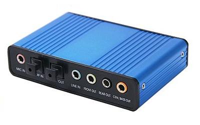
Unfortunately, it doesn't have a specific name or model number to search for. Try "USB 5.1 Sound" and look for a matching photo. The unit shown here was purchased from HDE through Amazon.
The device uses the C-Media CM6206 USB Audio I/O Controller chip. It provides 6 independent and equal output channels, any or all of which can be modified to be positive-only outputs.
Likewise, stereo Line inputs can be similarly modified to accept two positive-only input channels.
CM6206 Unipolar DC Outputs:
The output modification is simplest. This method was developed by Kamal Mostafa and is presented on his site <http://www.whence.com/soundcard-dc-dac/> , entitled DC coupled soundcard DAC mod. He is using this to drive a homebrew laser projector with his own software under Linux. After the modification, the output full-scale range is about +0.1 to +4.1 volts.
(Since the output voltage is used to control position in that application, the fact that the output does not go all the way down to zero volts is not a problem; only a simple mechanical adjustment would be needed to set the reference position.)
He uses a small 100 ohm surface-mount resistor to bridge the output capacitor of each output channel he uses. (He chose to retain normal AC coupling on the Front Left and Right channels, so only the remaining 4 channels receive this treatment.)
Note that in principle the resistor could be replaced with a straight piece of wire. The resistor, however, may provide extra protection in case the output is accidentally shorted to ground. This can happen momentarily, simply by plugging into the connector. So unless you intend to hard-wire this unit into your project, it's smart to use the resistor. (The CM6206 chip may have built-in limiting, but the specifications don't mention it.)
As discussed under Output and Reference Connections in the Sound Card DC Input / Output Modification topic below, the output capacitors are the row of 6 black electrolytics near the upper left in this image of the top of the USB board:
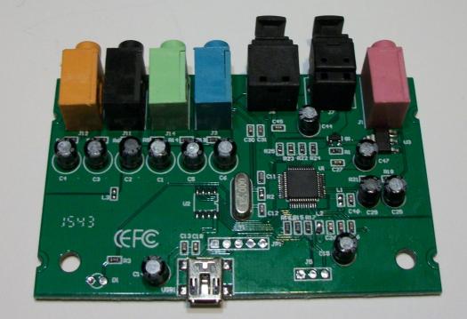
The capacitor numbering, starting from the right end of the row and moving left, is:
    C6  Front Left
    C5  Front Right
    C1  Rear Left
    C2  Rear Right
    C3  Center (Left)
    C4  Bass (Right)
These make more sense when viewed from the bottom:
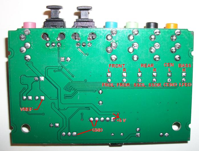
You can disregard most of the red labels. For our purposes here, note only the Front L and R, Rear L and R, Cen L, and Bass R locations.
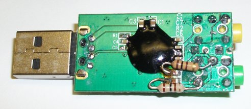
You don't need to use surface-mount resistors; standard 1/4 watt carbon film resistors work just fine. You will need to bend the leads into tight hooks and hold them carefully in place while you solder. The image below shows the Front L capacitor after being bridged by such a resistor.
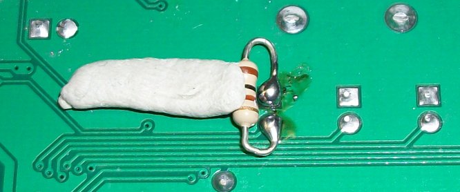
The gray blob on the left is a small section of sticky 'Mortite' rope caulking that held the resistor in position for soldering, and was subsequently moved for use on the next connection. Another alternative would be a tiny dab of hot glue, which could remain in place afterward. Just take care not to get any on the solder pads before you solder to them!
Note that the resistor must be very close to the board, with no glue, etc, rising much above it, in order to clear the metal housing when the board is inserted back into the case.
CM6206 Unipolar DC Output Calibration:
After bridging the output capacitors, the outputs will have the chip's internal reference voltage added to the generated signal. For the CM6206 that value is 2.25 V. Calibration consists of setting the Full-Scale Range to half the difference between the maximum and minimum voltages, and setting Data Zero Manual to compensate for the reference voltage.
Note that you can't change the Full-Scale Range setting unless an Auto-Calibration has been performed for this device.
To produce a DC output voltage that switches between the upper and lower full-scale limits at 5-second intervals, first load the Default.GEN Generator setup. This produces a 440 Hz Sine wave on the Left output stream, but since only the Left output enable is active the same signal will appear at both Left and Right outputs.
Click on the Left Wave Controls button and set the Wave type to Square and Tone Freq to 0.1 Hz.
Toggle the Generator on. The waveform display will show only the Left Output as a single horizontal green line, which will alternate between positive and negative full-scale every 5 seconds.
Now hit the F9 key to see the Volume Slider dialog. Make sure all sliders are fully up and Mutes are off. (On XP, there are separate Master and Wave sliders and Mute buttons.)
On Vista and later systems, right-click the speaker icon in the system tray and open the Windows Volume Mixer. Make sure that the Speakers slider is all the way up, and that any other sliders besides Daqarta's own are muted by clicking on the little speaker icon below each slider. In general it is always best to fully close all other applications that use the sound card before starting Daqarta. The Volume Mixer would then show only Speakers, Windows Sounds, and Daqarta sliders.
Connect a DMM to the Left Output and measure the highest and lowest values as the output cycles between them. The true full-scale range will be half the difference between these DMM readings. Enter that value under Wave Out in the Full-Scale Range dialog. If 5 seconds per state is too fast for accurate reading of your DMM, reduce the Tone Freq as desired.
Next change the Wave type back to Sine and Tone Freq to 0 Hz (DC). The waveform display will show a steady line at 0, which is what the Generator thinks it is outputting, but due to the output mods it will actually be generating the chip reference voltage. Use your DMM to measure that voltage; it should be close to +2.25 V for the CM6206.
Now open the Zero control dialog and toggle the Data Zero Manual radio button on. Toggle the Units button to Volts. Enter the negative of the reference voltage you just measured into the LO Adjust and RO Adjust controls.
Now the Voltmeter, cursor readouts, and Y-axis trace position (if no Input channel is also active) should all correspond to the true DMM value.
CM6206 Unipolar DC Inputs:
Input modifications are trickier, since the capacitors on this USB device are tiny surface-mount units (C30 and C31), as shown here:
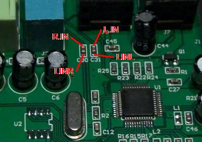
Use the same 100 ohm resistor bridge method as for outputs, soldering directly to the blocky contacts at either end of each capacitor chip.
CM6206 Unipolar DC Input Calibration:
With the input capacitors bridged, the CM6206 will by default report all input voltages relative to its internal reference of +2.25 V, which it calls zero. In other words, with the inputs disconnected (not grounded!) the CM6206 will report zero to Daqarta, just as it did before the capacitors were bridged. We can use Data Zero Manual to get zero to be reported as +2.25 V (see below), but other input values will only read correctly if the Full-Scale Range is calibrated.
Note that you can't change the Full-Scale Range values unless an Auto-Calibration has been performed.
To calibrate the Full-Scale Range, use an external DMM to measure the actual voltages of two ordinary 1.5 V batteries, which we will call V1 and V2. Now open the Input controls dialog and make sure both Left and Right buttons are active, and that Line In is selected, and the Input Level is -191.
Toggle the main Input button on and use the sound card to measure V1, with its '+' terminal connected to Left In (tip of stereo plug) and its '-' terminal connected to ground (shank of plug). Use the Daqarta Voltmeter or cursor readout and record the Left In value as Va.
Now put both batteries in series and repeat the Daqarta measurement, and record it as Vb. The signed difference between these (Vb - Va) is what Daqarta would measure as the V2 voltage. Let's say it is 1.23 V, and that the true V2 value is 1.60 V. We thus need to increase Daqarta's Full-Scale Range setting by the factor 1.60 / 1.23, or 1.3008. If the Line Input Full-Scale Range is still set to the default value of 1.00000, just enter 1.3008 instead; otherwise, multiply the value by 1.3008 and enter the product.
Now open the Zero control dialog and toggle the Data Zero Manual radio button on. Toggle the Units button to Volts. Re-measure the V1 battery with Daqarta, and enter that value minus the true DMM value into the LI Adjust and RI Adjust controls. The entered value should be close to -2.25 V.
Now the Daqarta Voltmeter, cursor readouts, and the Y-axis trace position should all match the true DMM value.
Note that this is only true with the Input Line Level at the least-sensitive range (-191), which would normally be about +/-1.50 volt full scale. Since the CM6206 measures relative to its internal +2.25 V reference, the range is now about +2.25 +/-1.50 V, or +0.75 to +3.75 volts. The CM6206 will clip larger or smaller signals to this range.
However, suppose you set the Input Line Level to its most-sensitive range (0), which would normally be about +/-0.040 V full scale. Now it will be limited to +2.25 +/-0.040 V, or +2.10 to 2.29 V... not very useful! (In addition, the Data Zero Manual control wouldn't allow you to get correct readings, since the control is limited to +/-100% of the full-scale range.)
2 Channel USB Plug-Type Sound Cards:
There are numerous very inexpensive USB sound devices built into oversized USB plugs. These have two audio jacks: The green one is for normal stereo outputs (though many claim "virtual" 5.1 or 7.1 channels, or "3D" sound, etc.) The other jack (typically yellow) is a single-channel microphone input that we will not modify. There are no Line inputs. Units discussed here can be found at less than US $10 each with free shipping from China.
DC Output Modification: The simple modification discussed here is to bridge the output capacitors with 100 ohm resistors, as discussed above under 5.1 Channel CM6206 USB Sound Card. That will essentially add the audio chip's internal reference voltage (typically 1.65 to 2.25 V) to the signal generated by Daqarta. That means the 0 point of the generated waveform will now be the reference voltage, with positive parts of the waveform becoming more positive, and negative parts becoming less positive but always above 0 volts.
Note that the reference is added after the volume control, such that lower volumes mean the modified output stays closer to the reference voltage, not closer to zero.
Thus, you will almost always want to run with the volume at maximum, to allow the widest output range. The devices discussed here have ranges of 0.6 to 2.7 V or 0.6 to 3.9 V.
0-5 V Pulse Outputs: If you need pulses to drive an external input that expects a 0-5 V signal, note that most such inputs accept the standard 'TTL' voltage range of 0.8 V or less for 'low' and 2.0 V or more for 'high'. That means that any of these modified USB devices should work. (But you do need to test your particular setup. See Sound Card DC Pulse Output Circuits for guaranteed 0-5 V outputs, including the Inexpensive All-In-One USB Device Modifications section.)
Opening The Case: All of the devices discussed here have plastic cases that simply snap together. There are prongs at the corners of the top that mate with holes in the bottom. The prongs are very easy to break off; to avoid that you must pull the top and bottom directly apart, with minimal tilting. Insert one fine-bladed (jeweller's) screwdriver between the top and the USB connector, and another between the top and bottom at the opposite (jack) end. Pry gently with both at the same time, then lift the top straight up. Alternatively, don't worry about breaking the prongs; you can easily hold the case together with tape.
Other USB Devices: If your USB device differs from the ones discussed below, you can still use the general approach covered here. You just need to identify the output capacitors. Sometimes you can do this simply by following the circuit board traces from the output jack connectors, but to be certain you should test for low-resistance connections. The best way is to insert a male-male audio cable into the jack. Set your meter to Ohms and measure between the tip of the plug on the free end of the cable, and the various solder pins under the connector on the circuit board. That will locate the Left output terminal.
Keeping the meter probe on the tip, test both ends of nearby capacitors until you find the one that has a direct connection to the Left output. That's the output capacitor you'll need to bridge. (The capacitors may be on the top or bottom of the circuit board.)
Now repeat with meter probe on the tiny ring of the plug, being careful not to let the probe short to the shank (ground) or the tip. That will locate the Right output terminal, and then the Right output capacitor.
Microphone Input: You may be wondering if you can similarly bridge the microphone input capacitor to allow DC inputs. There are several problems with this. The first is that microphone inputs have a microphone bias voltage applied to the input. In these USB devices it is via a 300 ohm resistor connected to the internal reference voltage (around 2 V). This not only represents a very low impedance (heavy load) for any input source to drive, but it also means the bias voltage will end up competing with the input signal. This problem could be solved by removing the 300 ohm resistor.
The next problem is that microphone inputs have high gain, since they typically deal with signals in the millivolt range. Unless the input sensitivity can be greatly reduced, you will only be able to measure input voltages that are near the chip reference voltage. In the case of the first device discussed below, the least-sensitive input range is +/-50 mV and the reference is +2.25 V, so you would only be able to measure inputs from +2.20 to +2.30 V... not very useful.
The final (and worst) problem is that even with the input capacitor bypassed, the audio chip apparently supplies additional AC coupling due to its built-in input filter. There is thus no point in bypassing the input capacitor, since you still can't measure DC voltages.
However, if you want to measure AC input voltages in addition to producing DC output voltages, the second and third devices both allow a wide range of inputs. Minimum sensitivity is about 3 Vpp with the Input level control at step -190. (The lowest step, -191, mutes the input entirely.)
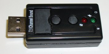
First Unit: Both the first and second units that we'll discuss look like this:
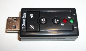
Search for 'virtual 7.1 channel USB sound adapter' and look for the above image. PLEASE NOTE: There are several models that use this identical case, and can't be distinguished before you purchase. They may have different internal layouts and use different audio chips. We'll discuss two different units here, both under US $10.
Since the first device uses a separate crystal that would increase production cost, it's reasonable to assume that the cheapest units will use a crystal-less design like the second unit (as does the third unit, with a different case). But paying more money will not guarantee that you get the crystal-based design.
The first unit is unbelievably easy to modify because it has large unused solder pads on the top side of the board for the insertion of additional output capacitors C20 (Right channel) and C21 (Left channel), which are connected in parallel with the existing capacitors C23 and C22, respectively, that are on the bottom side of the board.
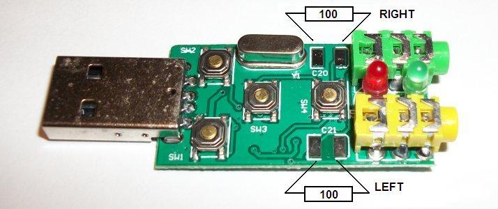
You just install 100 ohm resistors across these pads as described for the 5.1 Channel CM6206 device discussed above.
Other than simplicity, the main advantage of this device is that it has a fairly wide output range after modification, from about +0.6 to +3.9 V. (The other tested devices are +0.6 to +2.7 volts.)
Second Unit: The second seemingly-identical unit lacks the crystal, as well as the convenient solder pads:
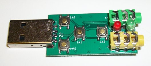
Instead, you have to solder to the tiny chip capacitors C8 and C9 on the bottom of the board:
Assuming you don't have surface-mount chip resistors that could be installed directly on top of C8 and C9, the image above shows a way to fit standard 1/4 watt carbon film resistors. One end of each resistor goes to the capacitor terminal that is closest to the black blob that covers the audio chip. The other end goes directly to the output jack, which is where the other end of the capacitor connects.
(The jack terminals closest to the capacitors connect to the tip of the audio plug, which is the Left channel. The middle terminal connects the Right channel to the "ring" on the plug, and the far terminals connect the shank of the plug to ground.)
It's easiest to solder the jack end of the resistor first, since you can loop it around the solder terminal to help hold it in place. You can use a small piece of tape or sticky rope caulking like 'Mortite' to hold the other end while you solder that first end, as in the CM6206 Unipolar DC Outputs topic above. Then, with the resistor now self-supporting, carefully bend and trim the remaining end to contact the far end of the capacitor. Apply a drop of flux to the joint and then solder, using a quick touch to avoid overheating the joint... the trace leading from there to the audio chip is very fine.
This device has a smaller output range than the first one, about +0.6 to +2.7 V.
Case and Button Issues: There are two minor shortcomings of the devices that use this case style: On some systems, the unit may be a little too wide to plug into a USB port that is adjacent to one already in use.
In addition, the unit has pushbuttons to increase or decrease the volume setting, as well as mutes for the output and input. (The latter are under the left and right edges of the large button next to the USB connector.) These buttons may be handy for normal use, but for unipolar DC output operation the volume must be kept at maximum in order to get the expected output voltage range. (Since the range will now be centered about the chip's internal reference voltage instead of about 0 volts, reducing the volume has the effect of raising the minimum positive voltage as well as reducing the maximum positive voltage.
This is easily dealt with by snipping off the plastic actuator rods from the buttons that operate the switches on the circuit board. The buttons will then need to be glued into to the top of the case, since they will no longer be supported by the switches. Before gluing, you may want to sand off the labels to help make it clear that the buttons are no longer functional:
Third Unit: The third unit we'll cover looks like this:
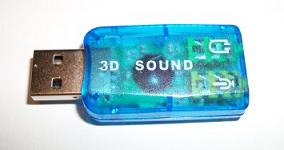
Search for 'Virtual 5.1 Surround USB Sound', or 'External 5.1 USB 3D Audio', or 'USB 3D Sound Card'. It's available in several colors.
There may be internal variations, but the two tested units look like this:
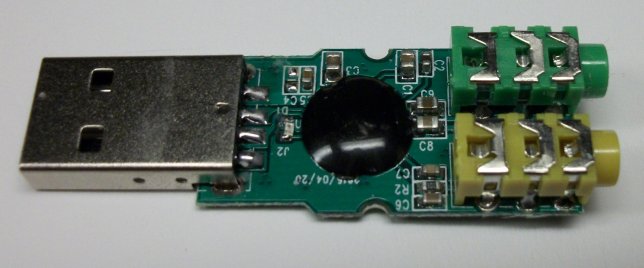
As with the second unit above, you need to bridge chip capacitors C8 and C9, which are just between the black blob and the jacks. Here, however, they are on the top of the board where there are no convenient solder terminals for the output jack. The simplest approach may be to bridge C9 by soldering one end of the resistor to the rear jack pin (Left output) on the bottom of the board, then bending it around so the resistor body is on the top side where you can solder to the black blob side of the capacitor.
The Right output capacitor C8 is a bit trickier. The best bet may be to solder directly to the middle connector (Right output) of the jack on the top side of the board, trying not to melt the plastic jack. Then connect to the black blob side of C8.
As with the second device, this has an output range from +0.6 to 2.7 V.
Calibration: Follow the steps in the CM6206 Unipolar DC Output Calibration section, except that for the second and third devices the reference voltage you will measure will be around 1.65 V instead of 2.25 as for the CM6206 and the first device.
See also External DC-to-AC Modulator, Sound Card DC Input / Output Modification, DC Measurements And Outputs
- Back to Sound Card DC Measurements And Outputs
- Ahead to Sound Card DC Input / Output Modification
- Daqarta Help Contents
- Daqarta Help Index
- Daqarta Downloads
- Daqarta Home Page
- Donate to Daqarta
Questions? Comments? Contact us!
We respond to ALL inquiries, typically within 24 hrs.INTERSTELLAR RESEARCH:
Over 45 Years of Innovative Instrumentation
© Copyright 2007 - 2026 by Interstellar Research
All rights reserved