Software for Windows
Science with your Sound Card!


Features:
Oscilloscope
Spectrum Analyzer
8-Channel
Signal Generator
Spectrogram
Pitch Tracker
Pitch-to-MIDI
DaqMusiq Generator
(Free Music... Forever!)
Engine Simulator
LCR Meter
Remote Operation
DC Measurements
True RMS Voltmeter
Sound Level Meter
Frequency Counter
Period
Event
Spectral Event
Temperature
Pressure
MHz Frequencies
Data Logger
Waveform Averager
Histogram
Post-Stimulus Time
Histogram (PSTH)
THD Meter
IMD Meter
Precision Phase Meter
Pulse Meter
Macro System
Multi-Trace Arrays
Trigger Controls
Auto-Calibration
Spectral Peak Track
Spectrum Limit Testing
Direct-to-Disk Recording
Accessibility
Data Logger
Waveform Averager
Histogram
Post-Stimulus Time
Histogram (PSTH)
THD Meter
IMD Meter
Precision Phase Meter
Pulse Meter
Macro System
Multi-Trace Arrays
Trigger Controls
Auto-Calibration
Spectral Peak Track
Spectrum Limit Testing
Direct-to-Disk Recording
Accessibility
Applications:
Frequency response
Distortion measurement
Speech and music
Microphone calibration
Loudspeaker test
Auditory phenomena
Musical instrument tuning
Animal sound
Evoked potentials
Rotating machinery
Automotive
Product test
Contact us about
your application!
Arduino_RCtime Multi-Pin Resistance/Capacitance Meter
- Introduction
- Features
- Operation
- Calibration
- Arduino_RCtime Macro Listing
Introduction:
The Arduino_RCtime macro mini-app demonstrates measurement of up to 6 resistors or capacitors using the 0xFC RCtime function of the DaqPort Arduino Sketch that is included with Daqarta.
This self-contained mini-app does not use Custom Controls, Multitasking, or macro subroutines, as do the DaquinOscope and DC Chart Recorder mini-apps. Instead, you edit variables at the start of the macro code to change operational modes, parameters, and pin usage.
The result of these simplifications is that the code is all in one listing, and is much easier to understand and customize for your own purposes.
Features:
Arduino_RCtime can simultaneously measure resistance or capacitance on any or all of Arduino digital input pins 2-7. It can use any of the 3 circuit configurations discussed under 0xFC RCtime function of the DaqPort Arduino Sketch.
You can run Arduino_RCtime in continuous mode, where readings are updated many times per second until you hit the SHIFT key to end operation. Alternatively, you can view a single update each time you run Arduino_RCtime. The latter may be useful if you are experimenting with various parameter settings, or your own custom modifications.
Note that for resistance measurement, Arduino_RCtime accuracy falls off rapidly below about 10K. (See the discussion and table in the 0xFC RCtime section of the DaqPort Arduino Sketch.) If you need to measure low values, add a series resistor of 10K or 100K, then subtract its value from the reported value.
Operation:
The Arduino_RCtime macro mini-app is included with Daqarta. To run it, first hit CTRL+F8 to open the Macro Dialog. Then scroll the Macro List down and double-click on Arduino_RCtime. (There is no single-letter ID for Hot Key access, as there is for the mini-apps at the top of the list.)
However, before you use Arduino_RCtime, you may want to change certain parameters that are set near the start of the macro. To edit these, single-click on Arduino_RCtime to select it without running it, then click the Edit button.
(Note that you can open this Help topic by selecting Arduino_RCtime as above, then clicking the Help button below the list, next to Run. Or, once you have opened the Edit dialog, you can click the duplicate Help button near the upper right.)
The default setup assumes you are measuring resistance on digital input pins 2 and 3 only. To use other pins, set the corresponding bits in variable QP at the start of the macro. Please note that you must use all pins that are set in this bitmap; unused pins may cause the RCtime function to hang while waiting for a response that never comes. It will not return until QT=1000 msec (1 second) has elapsed, which is the default Timeout delay.
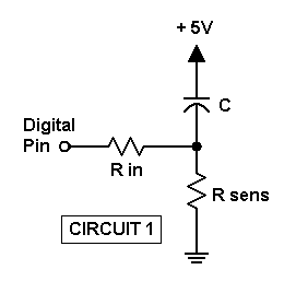
The default also makes assumptions about the circuit configuration on each pin, where Rsens is a resistive sensor (or other resistor to be measured), and C is a fixed reference capacitor that is initially charged or discharged through input resistor Rin, assumed to be 220 ohms. Note that any circuit can be used to measure a capacitive sensor using a fixed reference resistor. (More on this below.) The default assumes that each active pin is connected like Circuit 1:
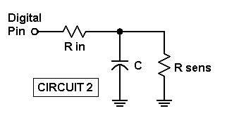
Or Circuit 2 with both Rsens and C grounded:
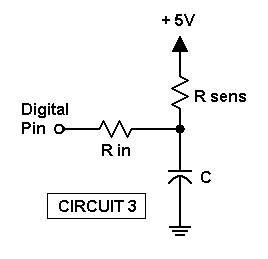
If you prefer to have Rsens at +5 and C grounded, change QG from 0 to 1 and use this Circuit 3:
To measure capacitance instead of resistance, change mode variable QM from 0 to 1.
Continuous measurement mode uses a time constant set via QC=100. You can reduce this value to get faster response if you don't mind more value jitter. Or you can increase the value for a more-stable display with sluggish response.
If you don't want continuous display updates, set QL=1 for single pass. In that case, the above time constant has no effect.
The display meter is resizeable during continuous operation by dragging its lower right corner. The default size is set via Mtr0="<F(30)". You can set another default as desired.
The RCtime process works by measuring the time to charge or discharge capacitor C through resistor Rsens. The time is proportional to the product of these, so in order to measure one you have to tell Arduino_RCtime the value of the other, which is held constant. For measuring resistance, array Buf0 holds the constant capacitor values for pins 2 through 7 in Buf0[12] through Buf0[17], and for measuring capacitance it holds the constant resistor values in Buf0[22] through Buf0[27].
Note that the resistors all default to 100K and the capacitors to 0.001 microfarad. You must make sure the values for the pins you are using are set to match the fixed capacitors or resistors you are using. There is no need for all pins to use the same value, and there is no need to set values for unused pins. See Calibration, below, for more information.
Tip: Note that the Arduino timer resolution is 4 microseconds. Using a large fixed value of resistance or capacitance will increase the measured time and hence increase the resolution of the final result.
However, note that the 1-second default Timeout delay may need to be increased if the product of resistance and capacitance is greater than that. (Ohms * microfarads = microseconds.) Divide microseconds by 1000 to get milliseconds, then enter that instead of the default QT=1000 near the start.
Likewise, if using large capacitors (microfarads), you may need to increase the default discharge (or charge) delay from its 1 millisecond default. The value should be should be at least five Rin * C time constants. Convert to milliseconds and enter that instead of the default QD=1 near the start.
When you run Arduino_RCtime it will show values for all pins 2-7, even those that are unused. At the bottom of the meter display you'll also see a report of the number of pins that failed out of the number selected via QP. Failed pins may be due to component disconnect, or values simply too large to measure before the Timeout expires.
Calibration:
You can calibrate Arduino_RCtime for your system if you have components whose values are known to the desired accuracy. The simplest approach is to adjust the constant values entered in Buf0. For example, if you want to calibrate for resistance measurement, start with the marked value of your actual fixed capacitor in the appropriate Buf0[12] to Buf0[17] location for the pin to be calibrated. Apply a known resistance and read the reported value. Divide the known value by the reported value, and multiply the relevant Buf0 capacitor entry by that factor.
Arduino_RCtime operates by measuring the time t to charge or discharge C through Rsens, where t = Rsens * C / K. Here K is a constant that reflects the starting and ending voltages. Since the Arduino rising and falling logic thresholds are different, the K value differs according to the circuit specified by QG.
The K value for QG=0 (Circuit 1 or Circuit 2, using the falling threshold) is stored in Buf0[30], while Buf0[31] stores the K value for QG=1 (Circuit 3, rising threshold). The default values were determined for a single Arduino test unit, and reflect thresholds in the typical specification range. But since the thresholds aren't guaranteed for any specific unit, yours may be slightly different.
You don't really need to adjust these if you are only measuring resistance, in which case you can just use the above pin-by-pin fixed capacitor value adjustment instead. This only requires a single precision resistor or ohmmeter.
Likewise, if you are only measuring capacitance and have a single precision capacitor or meter, you can simply adjust the fixed resistor values.
But if you have both a known resistor and a known capacitor, you can set one as fixed and measure the other with Arduino_RCtime. If the reported value is different from the known value, use the ratio to adjust the relevant K value (instead of the fixed value which you know is correct).
Please note that the K value also includes the effect of Rsens acting in a voltage divider with Rin to affect the starting voltage. This effect causes serious measurement issues when Rsens is below about 10K. (See the discussion and table in the 0xFC RCtime section of the DaqPort Arduino Sketch.)
The point here is that if you are going to adjust K, make sure that you are using a high Rsens. 100K or more is best.
This effect is not only an issue for resistance measurements; it can also affect capacitance measurements if you use a low fixed resistance.
Arduino_RCtime Macro Listing:
;<Help=H4925

QP=b00001100           ;Bits 2 and 3 set for pins to use
QG=0                   ;Config 0=R gnd, C +5.  1=C gnd, R +5
QM=0                   ;Mode 0=R, 1=C measurement
QT=1000                ;Timeout delay 1000 msec = 1 sec
QD=1                   ;Discharge/charge delay = 1 msec
QC=100                 ;Meter time constant
QL=0                   ;0 = continuous, else single pass
Mtr0="<F(30)"          ;Initial meter font size

Buf0="<=(0)"           ;Clear Buf0 values
Str7=                  ;Clear Str7 text

;Fixed C values for measuring R:
Buf0[12]=0.001         ;Fixed C for pin 2
Buf0[13]=0.001
Buf0[14]=0.001
Buf0[15]=0.001
Buf0[16]=0.001
Buf0[17]=0.001         ;Fixed C for pin 7

;Fixed R values for measuring C:
Buf0[22]=100k          ;Fixed R for pin 2
Buf0[23]=100k
Buf0[24]=100k
Buf0[25]=100k
Buf0[26]=100k
Buf0[27]=100k          ;Fixed R for pin 7

Buf0[30]=1.15          ;Default K value for R gnd, C +5)
Buf0[31]=1.33          ;Default for C gnd, R +5
K=Buf0[30 + QG]        ;Actual K in use

Str7[0]="0.0"          ;Integer-only format for R
Str7[10]="0.6"         ;6 decimal places for C
Str7[100]="Resistance, Ohms"
Str7[120]="Capacitance, uFd"

Posn#0="Ardu"          ;Specify Arduino only
Posn#1=0               ;Device count, 0 = first found
@_ComDev_Scan       ;Find and open COM device port

QM=QM & 1              ;Only allow 0 or 1
QG=QG & 1

IF.QL=0                ;Continuous loop?
    Mtr0="<<Hit SHIFT to exit Arduino_RCtime"  ;Mtr title for loop
ELSE.                  ;Else single-pass only
    Mtr0="<<Arduino_RCtime"
ENDIF.
Mtr0="Waiting for RCtime..."
Port=$(hF0) + "W" + $w(-QT)      ;Wait timeout = QT msec (1 sec)

WHILE.Key?$=0          ;Wait for SHIFT key
;RCtime on pins 3&4, R gnd, read usec, delay 1 msec (QD)
    Port=$(hFC) +$(QP + 2*QG) + $w(-QD)     ;Call RCtime in DaqPort
    U0=Port?5              ;U0=time, also sets Port?c
    UC=Port?c              ;Num chans from above Port?5

    UI=0
    WHILE.UI=<UC           ;For all pins in use:
        Port#D1=h80 + UI       ;Bit pattern of UIth hit
        Q0=Port?2
        UN=log2(Q0)            ;Max neg if Q0=0
        IF.UN=<0
            UN=0
        ENDIF.
        Port#D1=h90 + UI       ;Get time for this pin
        U0=Port?4              ;Time value, usec
        IF.QM=0                ;Measure R?
            X=U0 * K / Buf0[UN+10]     ;Find R = time * K / C_fixed
        ELSE.                  ;Else measure C
            X=U0 * K / Buf0[UN+20]     ;Find C = time * K / R_fixed
        ENDIF.
        A=Buf0[UN]             ;Prior value with QC time constant
        IF.A=0                 ;Initial reading?
            A=X                    ;Initialize with X
        ELSE.                  ;Else apply time constant with new X
            A=A - (A/QC) + (X/QC)
        ENDIF.
        Buf0[UN]=A             ;Save new value with TC applied
        UI=UI+1                ;Next pin
    WEND.

    Port#D1=h87            ;Get timeout count
    Q7=Port?2

    Mtr0="Pin     " + Str7[100 + 20 * QM] +n _
        + " 2       " + Buf0[2](Str7[10 * QM]) +n _
        + " 3       " + Buf0[3](Str7[10 * QM]) +n _
        + " 4       " + Buf0[4](Str7[10 * QM]) +n _
        + " 5       " + Buf0[5](Str7[10 * QM]) +n _
        + " 6       " + Buf0[6](Str7[10 * QM]) +n _
        + " 7       " + Buf0[7](Str7[10 * QM]) +n _
        + " Failed " + Q7 + " of " +UC +" pins"
    IF.QL=!0               ;Continuous loop mode?
        LoopBreak=2            ;Exit if not
    ENDIF.
WEND.                      ;Else continue until SHIFT key
Mtr0="<<Arduino RCtime Done"    ;Change meter title to show done
Port#O=0                   ;Close COM port
See also DaqPort Arduino Sketch, USB / Serial Communications Port Access, LCR Meter Mini-App with ESR, DF, and Q
- Back to Arduino_Oscillators Mini-App
- Ahead to Numato_Meter Mini-App
- Daqarta Help Contents
- Daqarta Help Index
- Daqarta Downloads
- Daqarta Home Page
- Donate to Daqarta
Questions? Comments? Contact us!
We respond to ALL inquiries, typically within 24 hrs.INTERSTELLAR RESEARCH:
Over 45 Years of Innovative Instrumentation
© Copyright 2007 - 2026 by Interstellar Research
All rights reserved